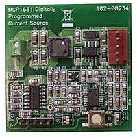
MCP1631RD-MCC1 Microchip Technology, MCP1631RD-MCC1 Datasheet - Page 78

MCP1631RD-MCC1
Manufacturer Part Number
MCP1631RD-MCC1
Description
REFERENCE DESIGN FOR MCP1631HV
Manufacturer
Microchip Technology
Type
Battery Managementr
Datasheets
1.MCP1631VHVT-330EST.pdf
(34 pages)
2.MCP1631HV-330EST.pdf
(54 pages)
3.MCP1631RD-MCC2.pdf
(20 pages)
4.MCP1631RD-MCC2.pdf
(328 pages)
5.MCP1631RD-MCC1.pdf
(28 pages)
Specifications of MCP1631RD-MCC1
Main Purpose
Power Management, Battery Charger
Embedded
Yes, MCU, 8-Bit
Utilized Ic / Part
MCP1631HV, PIC16F883
Primary Attributes
1 ~ 2 Cell- Li-Ion, 1 ~ 4 Cell- NiCd/NiMH
Secondary Attributes
Status LEDs
Supported Devices
MCP1631HV, PIC16F883 Device Type
Tool / Board Applications
Power Management-Battery Management
Development Tool Type
Reference Design
Input Voltage
5.5 V to 16 V
Product
Power Management Modules
Mcu Supported Families
MCP1631HV/PIC16F883 Family
Silicon Manufacturer
Microchip
Silicon Core Number
MCP1631HV
Kit Application Type
Reference Design
Application Sub Type
Battery Charger
Kit Contents
Board Only
Lead Free Status / RoHS Status
Lead free / RoHS Compliant
For Use With/related Products
MCP1631HV, PIC16F883
Lead Free Status / RoHS Status
Lead free / RoHS Compliant
- MCP1631VHVT-330EST PDF datasheet
- MCP1631HV-330EST PDF datasheet #2
- MCP1631RD-MCC2 PDF datasheet #3
- MCP1631RD-MCC2 PDF datasheet #4
- MCP1631RD-MCC1 PDF datasheet #5
- Current page: 78 of 328
- Download datasheet (6Mb)
PIC16F882/883/884/886/887
6.0
The Timer1 module is a 16-bit timer/counter with the
following features:
• 16-bit timer/counter register pair (TMR1H:TMR1L)
• Programmable internal or external clock source
• 3-bit prescaler
• Optional LP oscillator
• Synchronous or asynchronous operation
• Timer1 gate (count enable) via comparator or
• Interrupt on overflow
• Wake-up on overflow (external clock,
• Time base for the Capture/Compare function
• Special Event Trigger (with ECCP)
• Comparator output synchronization to Timer1
Figure 6-1 is a block diagram of the Timer1 module.
FIGURE 6-1:
DS41291F-page 76
T1G pin
Asynchronous mode only)
clock
Without CLKOUT
T1OSO/T1CKI
TIMER1 MODULE WITH GATE
CONTROL
T1OSCEN
Note 1:
INTOSC
T1OSI
T1G
Set flag bit
TMR1IF on
Overflow
2:
3:
4:
ST Buffer is low power type when using LP osc, or high speed type when using T1CKI.
Timer1 register increments on rising edge.
Synchronize does not operate while in Sleep.
SYNCC2OUT is synchronized when the C2SYNC bit of the CM2CON1 register is set.
TIMER1 BLOCK DIAGRAM
Oscillator
TMR1H
TMR1
(2)
TMR1L
Internal
F
OSC
Clock
EN
(1)
/4
6.1
The Timer1 module is a 16-bit incrementing counter
which is accessed through the TMR1H:TMR1L register
pair. Writes to TMR1H or TMR1L directly update the
counter.
When used with an internal clock source, the module is
a timer. When used with an external clock source, the
module can be used as either a timer or counter.
6.2
The TMR1CS bit of the T1CON register is used to select
the clock source. When TMR1CS = 0, the clock source
is F
supplied externally.
TMR1CS
F
T1CKI pin
OSC
1
0
To C2 Comparator Module
Timer1 Clock
OSC
/4
/4. When TMR1CS = 1, the clock source is
Timer1 Operation
Clock Source Selection
T1CKPS<1:0>
Clock Source
T1SYNC
Prescaler
1, 2, 4, 8
SYNCC2OUT
TMR1ON
0
1
2
© 2009 Microchip Technology Inc.
TMR1GE
(4)
Synchronized
Synchronize
clock input
T1GSS
1
0
det
(3)
TMR1CS
T1GINV
0
1
Related parts for MCP1631RD-MCC1
Image
Part Number
Description
Manufacturer
Datasheet
Request
R

Part Number:
Description:
REFERENCE DESIGN MCP1631HV
Manufacturer:
Microchip Technology
Datasheet:

Part Number:
Description:
REF DES BATT CHARG OR LED DRIVER
Manufacturer:
Microchip Technology
Datasheet:

Part Number:
Description:
Manufacturer:
Microchip Technology Inc.
Datasheet:

Part Number:
Description:
Manufacturer:
Microchip Technology Inc.
Datasheet:

Part Number:
Description:
Manufacturer:
Microchip Technology Inc.
Datasheet:

Part Number:
Description:
Manufacturer:
Microchip Technology Inc.
Datasheet:

Part Number:
Description:
Manufacturer:
Microchip Technology Inc.
Datasheet:

Part Number:
Description:
Manufacturer:
Microchip Technology Inc.
Datasheet:

Part Number:
Description:
Manufacturer:
Microchip Technology Inc.
Datasheet:

Part Number:
Description:
Manufacturer:
Microchip Technology Inc.
Datasheet:


