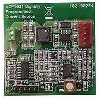
MCP1631RD-MCC1 Microchip Technology, MCP1631RD-MCC1 Datasheet - Page 221

MCP1631RD-MCC1
Manufacturer Part Number
MCP1631RD-MCC1
Description
REFERENCE DESIGN FOR MCP1631HV
Manufacturer
Microchip Technology
Type
Battery Managementr
Datasheets
1.MCP1631VHVT-330EST.pdf
(34 pages)
2.MCP1631HV-330EST.pdf
(54 pages)
3.MCP1631RD-MCC2.pdf
(20 pages)
4.MCP1631RD-MCC2.pdf
(328 pages)
5.MCP1631RD-MCC1.pdf
(28 pages)
Specifications of MCP1631RD-MCC1
Main Purpose
Power Management, Battery Charger
Embedded
Yes, MCU, 8-Bit
Utilized Ic / Part
MCP1631HV, PIC16F883
Primary Attributes
1 ~ 2 Cell- Li-Ion, 1 ~ 4 Cell- NiCd/NiMH
Secondary Attributes
Status LEDs
Supported Devices
MCP1631HV, PIC16F883 Device Type
Tool / Board Applications
Power Management-Battery Management
Development Tool Type
Reference Design
Input Voltage
5.5 V to 16 V
Product
Power Management Modules
Mcu Supported Families
MCP1631HV/PIC16F883 Family
Silicon Manufacturer
Microchip
Silicon Core Number
MCP1631HV
Kit Application Type
Reference Design
Application Sub Type
Battery Charger
Kit Contents
Board Only
Lead Free Status / RoHS Status
Lead free / RoHS Compliant
For Use With/related Products
MCP1631HV, PIC16F883
Lead Free Status / RoHS Status
Lead free / RoHS Compliant
- MCP1631VHVT-330EST PDF datasheet
- MCP1631HV-330EST PDF datasheet #2
- MCP1631RD-MCC2 PDF datasheet #3
- MCP1631RD-MCC2 PDF datasheet #4
- MCP1631RD-MCC1 PDF datasheet #5
- Current page: 221 of 328
- Download datasheet (6Mb)
TABLE 14-4:
TABLE 14-5:
© 2009 Microchip Technology Inc.
CM2CON1
EEDAT
EEADR
EEDATH
EEADRH
SRCON
BAUDCTL
ANSEL
ANSELH
EECON1
EECON2
Legend: u = unchanged, x = unknown, – = unimplemented bit, reads as ‘0’, q = value depends on condition.
Note 1:
Power-on Reset
MCLR Reset during normal operation
MCLR Reset during Sleep
WDT Reset
WDT Wake-up
Brown-out Reset
Interrupt Wake-up from Sleep
Legend: u = unchanged, x = unknown, — = unimplemented bit, reads as ‘0’.
Note 1:
Register
2:
3:
4:
5:
6:
If V
One or more bits in INTCON and/or PIR1 will be affected (to cause wake-up).
When the wake-up is due to an interrupt and the GIE bit is set, the PC is loaded with the interrupt
vector (0004h).
See Table 14-5 for Reset value for specific condition.
If Reset was due to brown-out, then bit 0 = 0. All other Resets will cause bit 0 = u.
Accessible only when SSPCON register bits SSPM<3:0> = 1001.
When the wake-up is due to an interrupt and Global Interrupt Enable bit, GIE, is set, the PC is loaded with
the interrupt vector (0004h) after execution of PC + 1.
DD
Condition
INITIALIZATION CONDITION FOR REGISTER (CONTINUED)
INITIALIZATION CONDITION FOR SPECIAL REGISTERS
goes too low, Power-on Reset will be activated and registers will be affected differently.
Address
10Ch
10Dh
18Ch
18Dh
10Eh
10Fh
109h
185h
187h
188h
189h
0000 0--0
0000 0000
0000 0000
--00 0000
---0 0000
0000 00-0
01-0 0-00
1111 1111
1111 1111
---- x000
---- ----
Power-on
Reset
PIC16F882/883/884/886/887
Program
PC + 1
Counter
WDT Reset (Continued)
PC + 1
000h
000h
000h
000h
000h
Brown-out Reset
MCLR Reset
0000 0--0
0000 0000
0000 0000
--00 0000
---0 0000
0000 00-0
01-0 0-00
1111 1111
1111 1111
---- q000
---- ----
(1)
(1)
0001 1xxx
000u uuuu
0001 0uuu
0000 uuuu
uuu0 0uuu
0001 1uuu
uuu1 0uuu
Register
Status
Wake-up from Sleep through
Wake-up from Sleep through
WDT Time-out (Continued)
uuuu u--u
uuuu uuuu
uuuu uuuu
--uu uuuu
---u uuuu
uuuu uu-u
uu-u u-uu
uuuu uuuu
uuuu uuuu
---- uuuu
---- ----
Interrupt
DS41291F-page 219
--01 --0x
--0u --uu
--0u --uu
--0u --uu
--uu --uu
--01 --u0
--uu --uu
Register
PCON
Related parts for MCP1631RD-MCC1
Image
Part Number
Description
Manufacturer
Datasheet
Request
R

Part Number:
Description:
REFERENCE DESIGN MCP1631HV
Manufacturer:
Microchip Technology
Datasheet:

Part Number:
Description:
REF DES BATT CHARG OR LED DRIVER
Manufacturer:
Microchip Technology
Datasheet:

Part Number:
Description:
Manufacturer:
Microchip Technology Inc.
Datasheet:

Part Number:
Description:
Manufacturer:
Microchip Technology Inc.
Datasheet:

Part Number:
Description:
Manufacturer:
Microchip Technology Inc.
Datasheet:

Part Number:
Description:
Manufacturer:
Microchip Technology Inc.
Datasheet:

Part Number:
Description:
Manufacturer:
Microchip Technology Inc.
Datasheet:

Part Number:
Description:
Manufacturer:
Microchip Technology Inc.
Datasheet:

Part Number:
Description:
Manufacturer:
Microchip Technology Inc.
Datasheet:

Part Number:
Description:
Manufacturer:
Microchip Technology Inc.
Datasheet:


