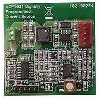
MCP1631RD-MCC1 Microchip Technology, MCP1631RD-MCC1 Datasheet - Page 71

MCP1631RD-MCC1
Manufacturer Part Number
MCP1631RD-MCC1
Description
REFERENCE DESIGN FOR MCP1631HV
Manufacturer
Microchip Technology
Type
Battery Managementr
Datasheets
1.MCP1631VHVT-330EST.pdf
(34 pages)
2.MCP1631HV-330EST.pdf
(54 pages)
3.MCP1631RD-MCC2.pdf
(20 pages)
4.MCP1631RD-MCC2.pdf
(328 pages)
5.MCP1631RD-MCC1.pdf
(28 pages)
Specifications of MCP1631RD-MCC1
Main Purpose
Power Management, Battery Charger
Embedded
Yes, MCU, 8-Bit
Utilized Ic / Part
MCP1631HV, PIC16F883
Primary Attributes
1 ~ 2 Cell- Li-Ion, 1 ~ 4 Cell- NiCd/NiMH
Secondary Attributes
Status LEDs
Supported Devices
MCP1631HV, PIC16F883 Device Type
Tool / Board Applications
Power Management-Battery Management
Development Tool Type
Reference Design
Input Voltage
5.5 V to 16 V
Product
Power Management Modules
Mcu Supported Families
MCP1631HV/PIC16F883 Family
Silicon Manufacturer
Microchip
Silicon Core Number
MCP1631HV
Kit Application Type
Reference Design
Application Sub Type
Battery Charger
Kit Contents
Board Only
Lead Free Status / RoHS Status
Lead free / RoHS Compliant
For Use With/related Products
MCP1631HV, PIC16F883
Lead Free Status / RoHS Status
Lead free / RoHS Compliant
- MCP1631VHVT-330EST PDF datasheet
- MCP1631HV-330EST PDF datasheet #2
- MCP1631RD-MCC2 PDF datasheet #3
- MCP1631RD-MCC2 PDF datasheet #4
- MCP1631RD-MCC1 PDF datasheet #5
- Current page: 71 of 328
- Download datasheet (6Mb)
4.6
The system clock source can be switched between
external and internal clock sources via software using
the System Clock Select (SCS) bit of the OSCCON
register.
4.6.1
The System Clock Select (SCS) bit of the OSCCON
register selects the system clock source that is used for
the CPU and peripherals.
• When the SCS bit of the OSCCON register = 0,
• When the SCS bit of the OSCCON register = 1,
4.6.2
The Oscillator Start-up Time-out Status (OSTS) bit of
the OSCCON register indicates whether the system
clock is running from the external clock source, as
defined by the FOSC<2:0> bits in the Configuration
Word Register 1 (CONFIG1), or from the internal clock
source. In particular, OSTS indicates that the Oscillator
Start-up Timer (OST) has timed out for LP, XT or HS
modes.
4.7
Two-Speed Start-up mode provides additional power
savings by minimizing the latency between external
oscillator start-up and code execution. In applications
that make heavy use of the Sleep mode, Two-Speed
Start-up will remove the external oscillator start-up
time from the time spent awake and can reduce the
overall power consumption of the device.
This mode allows the application to wake-up from
Sleep, perform a few instructions using the INTOSC
as the clock source and go back to Sleep without
waiting for the primary oscillator to become stable.
© 2009 Microchip Technology Inc.
the system clock source is determined by
configuration of the FOSC<2:0> bits in the
Configuration Word Register 1 (CONFIG1).
the system clock source is chosen by the internal
oscillator frequency selected by the IRCF<2:0>
bits of the OSCCON register. After a Reset, the
SCS bit of the OSCCON register is always
cleared.
Note:
Note:
Clock Switching
Two-Speed Clock Start-up Mode
SYSTEM CLOCK SELECT (SCS) BIT
Any automatic clock switch, which may
occur from Two-Speed Start-up or Fail-Safe
Clock Monitor, does not update the SCS bit
of the OSCCON register. The user can
monitor the OSTS bit of the OSCCON
register to determine the current system
clock source.
OSCILLATOR START-UP TIME-OUT
STATUS (OSTS) BIT
Executing a SLEEP instruction will abort
the oscillator start-up time and will cause
the OSTS bit of the OSCCON register to
remain clear.
PIC16F882/883/884/886/887
When the oscillator module is configured for LP, XT or
HS modes, the Oscillator Start-up Timer (OST) is
enabled (see Section 4.4.1 “Oscillator Start-up Timer
(OST)”). The OST will suspend program execution until
1024 oscillations are counted. Two-Speed Start-up
mode minimizes the delay in code execution by
operating from the internal oscillator as the OST is
counting. When the OST count reaches 1024 and the
OSTS bit of the OSCCON register is set, program
execution switches to the external oscillator.
4.7.1
Two-Speed Start-up mode is configured by the
following settings:
• IESO (of the Configuration Word Register 1) = 1;
• SCS (of the OSCCON register) = 0.
• FOSC<2:0> bits in the Configuration Word
Two-Speed Start-up mode is entered after:
• Power-on Reset (POR) and, if enabled, after
• Wake-up from Sleep.
If the external clock oscillator is configured to be
anything other than LP, XT or HS mode, then Two-
speed Start-up is disabled. This is because the external
clock oscillator does not require any stabilization time
after POR or an exit from Sleep.
4.7.2
1.
2.
3.
4.
5.
6.
7.
Internal/External Switchover bit (Two-Speed Start-
up mode enabled).
Register 1 (CONFIG1) configured for LP, XT or
HS mode.
Power-up Timer (PWRT) has expired, or
Wake-up from Power-on Reset or Sleep.
Instructions begin execution by the internal
oscillator at the frequency set in the IRCF<2:0>
bits of the OSCCON register.
OST enabled to count 1024 clock cycles.
OST timed out, wait for falling edge of the
internal oscillator.
OSTS is set.
System clock held low until the next falling edge
of new clock (LP, XT or HS mode).
System clock is switched to external clock
source.
TWO-SPEED START-UP MODE
CONFIGURATION
TWO-SPEED START-UP
SEQUENCE
DS41291F-page 69
Related parts for MCP1631RD-MCC1
Image
Part Number
Description
Manufacturer
Datasheet
Request
R

Part Number:
Description:
REFERENCE DESIGN MCP1631HV
Manufacturer:
Microchip Technology
Datasheet:

Part Number:
Description:
REF DES BATT CHARG OR LED DRIVER
Manufacturer:
Microchip Technology
Datasheet:

Part Number:
Description:
Manufacturer:
Microchip Technology Inc.
Datasheet:

Part Number:
Description:
Manufacturer:
Microchip Technology Inc.
Datasheet:

Part Number:
Description:
Manufacturer:
Microchip Technology Inc.
Datasheet:

Part Number:
Description:
Manufacturer:
Microchip Technology Inc.
Datasheet:

Part Number:
Description:
Manufacturer:
Microchip Technology Inc.
Datasheet:

Part Number:
Description:
Manufacturer:
Microchip Technology Inc.
Datasheet:

Part Number:
Description:
Manufacturer:
Microchip Technology Inc.
Datasheet:

Part Number:
Description:
Manufacturer:
Microchip Technology Inc.
Datasheet:


