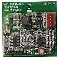
MCP1631RD-MCC1 Microchip Technology, MCP1631RD-MCC1 Datasheet - Page 42

MCP1631RD-MCC1
Manufacturer Part Number
MCP1631RD-MCC1
Description
REFERENCE DESIGN FOR MCP1631HV
Manufacturer
Microchip Technology
Type
Battery Managementr
Datasheets
1.MCP1631VHVT-330EST.pdf
(34 pages)
2.MCP1631HV-330EST.pdf
(54 pages)
3.MCP1631RD-MCC2.pdf
(20 pages)
4.MCP1631RD-MCC2.pdf
(328 pages)
5.MCP1631RD-MCC1.pdf
(28 pages)
Specifications of MCP1631RD-MCC1
Main Purpose
Power Management, Battery Charger
Embedded
Yes, MCU, 8-Bit
Utilized Ic / Part
MCP1631HV, PIC16F883
Primary Attributes
1 ~ 2 Cell- Li-Ion, 1 ~ 4 Cell- NiCd/NiMH
Secondary Attributes
Status LEDs
Supported Devices
MCP1631HV, PIC16F883 Device Type
Tool / Board Applications
Power Management-Battery Management
Development Tool Type
Reference Design
Input Voltage
5.5 V to 16 V
Product
Power Management Modules
Mcu Supported Families
MCP1631HV/PIC16F883 Family
Silicon Manufacturer
Microchip
Silicon Core Number
MCP1631HV
Kit Application Type
Reference Design
Application Sub Type
Battery Charger
Kit Contents
Board Only
Lead Free Status / RoHS Status
Lead free / RoHS Compliant
For Use With/related Products
MCP1631HV, PIC16F883
Lead Free Status / RoHS Status
Lead free / RoHS Compliant
- MCP1631VHVT-330EST PDF datasheet
- MCP1631HV-330EST PDF datasheet #2
- MCP1631RD-MCC2 PDF datasheet #3
- MCP1631RD-MCC2 PDF datasheet #4
- MCP1631RD-MCC1 PDF datasheet #5
- Current page: 42 of 328
- Download datasheet (6Mb)
PIC16F882/883/884/886/887
3.2
RA0 also has an Ultra Low-Power Wake-up option. The
next three sections describe these functions.
3.2.1
The ANSEL register (Register 3-3) is used to configure
the Input mode of an I/O pin to analog. Setting the
appropriate ANSEL bit high will cause all digital reads
on the pin to be read as ‘0’ and allow analog functions
on the pin to operate correctly.
The state of the ANSEL bits has no affect on digital out-
put functions. A pin with TRIS clear and ANSEL set will
still operate as a digital output, but the Input mode will
be analog. This can cause unexpected behavior when
executing
affected port.
REGISTER 3-3:
DS41291F-page 40
bit 7
Legend:
R = Readable bit
-n = Value at POR
bit 7-0
Note 1:
ANS7
R/W-1
2:
Additional Pin Functions
(2)
Setting a pin to an analog input automatically disables the digital input circuitry, weak pull-ups, and
interrupt-on-change if available. The corresponding TRIS bit must be set to Input mode in order to allow
external control of the voltage on the pin.
Not implemented on PIC16F883/886.
ANSEL REGISTER
read-modify-write
ANS<7:0>: Analog Select bits
Analog select between analog or digital function on pins AN<7:0>, respectively.
1 = Analog input. Pin is assigned as analog input
0 = Digital I/O. Pin is assigned to port or special function.
ANS6
R/W-1
ANSEL: ANALOG SELECT REGISTER
(2)
W = Writable bit
‘1’ = Bit is set
instructions
ANS5
R/W-1
(2)
on
R/W-1
ANS4
the
U = Unimplemented bit, read as ‘0’
‘0’ = Bit is cleared
R/W-1
ANS3
(1)
.
R/W-1
ANS2
© 2009 Microchip Technology Inc.
x = Bit is unknown
R/W-1
ANS1
R/W-1
ANS0
bit 0
Related parts for MCP1631RD-MCC1
Image
Part Number
Description
Manufacturer
Datasheet
Request
R

Part Number:
Description:
REFERENCE DESIGN MCP1631HV
Manufacturer:
Microchip Technology
Datasheet:

Part Number:
Description:
REF DES BATT CHARG OR LED DRIVER
Manufacturer:
Microchip Technology
Datasheet:

Part Number:
Description:
Manufacturer:
Microchip Technology Inc.
Datasheet:

Part Number:
Description:
Manufacturer:
Microchip Technology Inc.
Datasheet:

Part Number:
Description:
Manufacturer:
Microchip Technology Inc.
Datasheet:

Part Number:
Description:
Manufacturer:
Microchip Technology Inc.
Datasheet:

Part Number:
Description:
Manufacturer:
Microchip Technology Inc.
Datasheet:

Part Number:
Description:
Manufacturer:
Microchip Technology Inc.
Datasheet:

Part Number:
Description:
Manufacturer:
Microchip Technology Inc.
Datasheet:

Part Number:
Description:
Manufacturer:
Microchip Technology Inc.
Datasheet:


