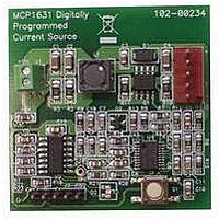
MCP1631RD-MCC1 Microchip Technology, MCP1631RD-MCC1 Datasheet - Page 133

MCP1631RD-MCC1
Manufacturer Part Number
MCP1631RD-MCC1
Description
REFERENCE DESIGN FOR MCP1631HV
Manufacturer
Microchip Technology
Type
Battery Managementr
Datasheets
1.MCP1631VHVT-330EST.pdf
(34 pages)
2.MCP1631HV-330EST.pdf
(54 pages)
3.MCP1631RD-MCC2.pdf
(20 pages)
4.MCP1631RD-MCC2.pdf
(328 pages)
5.MCP1631RD-MCC1.pdf
(28 pages)
Specifications of MCP1631RD-MCC1
Main Purpose
Power Management, Battery Charger
Embedded
Yes, MCU, 8-Bit
Utilized Ic / Part
MCP1631HV, PIC16F883
Primary Attributes
1 ~ 2 Cell- Li-Ion, 1 ~ 4 Cell- NiCd/NiMH
Secondary Attributes
Status LEDs
Supported Devices
MCP1631HV, PIC16F883 Device Type
Tool / Board Applications
Power Management-Battery Management
Development Tool Type
Reference Design
Input Voltage
5.5 V to 16 V
Product
Power Management Modules
Mcu Supported Families
MCP1631HV/PIC16F883 Family
Silicon Manufacturer
Microchip
Silicon Core Number
MCP1631HV
Kit Application Type
Reference Design
Application Sub Type
Battery Charger
Kit Contents
Board Only
Lead Free Status / RoHS Status
Lead free / RoHS Compliant
For Use With/related Products
MCP1631HV, PIC16F883
Lead Free Status / RoHS Status
Lead free / RoHS Compliant
- MCP1631VHVT-330EST PDF datasheet
- MCP1631HV-330EST PDF datasheet #2
- MCP1631RD-MCC2 PDF datasheet #3
- MCP1631RD-MCC2 PDF datasheet #4
- MCP1631RD-MCC1 PDF datasheet #5
- Current page: 133 of 328
- Download datasheet (6Mb)
11.5.4
In Sleep mode, the TMR2 register will not increment
and the state of the module will not change. If the CCPx
pin is driving a value, it will continue to drive that value.
When the device wakes up, TMR2 will continue from its
previous state.
11.5.5
The PWM frequency is derived from the system clock
frequency. Any changes in the system clock frequency
will result in changes to the PWM frequency. See
Section 4.0 “Oscillator Module (With Fail-Safe
Clock Monitor)” for additional details.
11.5.6
Any Reset will force all ports to Input mode and the
CCP registers to their Reset states.
© 2009 Microchip Technology Inc.
OPERATION IN SLEEP MODE
CHANGES IN SYSTEM CLOCK
FREQUENCY
EFFECTS OF RESET
PIC16F882/883/884/886/887
11.5.7
The following steps should be taken when configuring
the CCP module for PWM operation:
1.
2.
3.
4.
5.
6.
Disable the PWM pin (CCPx) output drivers as
an input by setting the associated TRIS bit.
Set the PWM period by loading the PR2 register.
Configure the CCP module for the PWM mode
by loading the CCPxCON register with the
appropriate values.
Set the PWM duty cycle by loading the CCPRxL
register and DCxB<1:0> bits of the CCPxCON
register.
Configure and start Timer2:
• Clear the TMR2IF interrupt flag bit of the
• Set the Timer2 prescale value by loading the
• Enable Timer2 by setting the TMR2ON bit of
Enable PWM output after a new PWM cycle has
started:
• Wait until Timer2 overflows (TMR2IF bit of
• Enable the CCPx pin output driver by clearing
PIR1 register.
T2CKPS bits of the T2CON register.
the T2CON register.
the PIR1 register is set).
the associated TRIS bit.
SETUP FOR PWM OPERATION
DS41291F-page 131
Related parts for MCP1631RD-MCC1
Image
Part Number
Description
Manufacturer
Datasheet
Request
R

Part Number:
Description:
REFERENCE DESIGN MCP1631HV
Manufacturer:
Microchip Technology
Datasheet:

Part Number:
Description:
REF DES BATT CHARG OR LED DRIVER
Manufacturer:
Microchip Technology
Datasheet:

Part Number:
Description:
Manufacturer:
Microchip Technology Inc.
Datasheet:

Part Number:
Description:
Manufacturer:
Microchip Technology Inc.
Datasheet:

Part Number:
Description:
Manufacturer:
Microchip Technology Inc.
Datasheet:

Part Number:
Description:
Manufacturer:
Microchip Technology Inc.
Datasheet:

Part Number:
Description:
Manufacturer:
Microchip Technology Inc.
Datasheet:

Part Number:
Description:
Manufacturer:
Microchip Technology Inc.
Datasheet:

Part Number:
Description:
Manufacturer:
Microchip Technology Inc.
Datasheet:

Part Number:
Description:
Manufacturer:
Microchip Technology Inc.
Datasheet:


