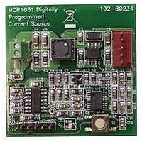
MCP1631RD-MCC1 Microchip Technology, MCP1631RD-MCC1 Datasheet - Page 317

MCP1631RD-MCC1
Manufacturer Part Number
MCP1631RD-MCC1
Description
REFERENCE DESIGN FOR MCP1631HV
Manufacturer
Microchip Technology
Type
Battery Managementr
Datasheets
1.MCP1631VHVT-330EST.pdf
(34 pages)
2.MCP1631HV-330EST.pdf
(54 pages)
3.MCP1631RD-MCC2.pdf
(20 pages)
4.MCP1631RD-MCC2.pdf
(328 pages)
5.MCP1631RD-MCC1.pdf
(28 pages)
Specifications of MCP1631RD-MCC1
Main Purpose
Power Management, Battery Charger
Embedded
Yes, MCU, 8-Bit
Utilized Ic / Part
MCP1631HV, PIC16F883
Primary Attributes
1 ~ 2 Cell- Li-Ion, 1 ~ 4 Cell- NiCd/NiMH
Secondary Attributes
Status LEDs
Supported Devices
MCP1631HV, PIC16F883 Device Type
Tool / Board Applications
Power Management-Battery Management
Development Tool Type
Reference Design
Input Voltage
5.5 V to 16 V
Product
Power Management Modules
Mcu Supported Families
MCP1631HV/PIC16F883 Family
Silicon Manufacturer
Microchip
Silicon Core Number
MCP1631HV
Kit Application Type
Reference Design
Application Sub Type
Battery Charger
Kit Contents
Board Only
Lead Free Status / RoHS Status
Lead free / RoHS Compliant
For Use With/related Products
MCP1631HV, PIC16F883
Lead Free Status / RoHS Status
Lead free / RoHS Compliant
INDEX
A
A/D
Absolute Maximum Ratings .............................................. 245
AC Characteristics
ACKSTAT ......................................................................... 198
ACKSTAT Status Flag ...................................................... 198
ADC .................................................................................... 99
ADCON0 Register............................................................. 104
ADCON1 Register............................................................. 105
ADRESH Register (ADFM = 0) ......................................... 106
ADRESH Register (ADFM = 1) ......................................... 106
ADRESL Register (ADFM = 0).......................................... 106
ADRESL Register (ADFM = 1).......................................... 106
Analog Input Connection Considerations............................ 90
Analog-to-Digital Converter. See ADC
ANSEL Register .................................................................. 40
ANSELH Register ............................................................... 48
Assembler
B
Baud Rate Generator ........................................................ 195
BAUDCTL Register ........................................................... 162
BF ..................................................................................... 198
BF Status Flag .................................................................. 198
Block Diagrams
© 2009 Microchip Technology Inc.
Specifications.................................................... 263, 264
Industrial and Extended ............................................ 255
Load Conditions ........................................................ 254
Acquisition Requirements ......................................... 107
Associated Registers ................................................ 109
Block Diagram............................................................. 99
Calculating Acquisition Time..................................... 107
Channel Selection..................................................... 100
Configuration............................................................. 100
Configuring Interrupt ................................................. 103
Conversion Clock...................................................... 100
Conversion Procedure .............................................. 103
Internal Sampling Switch (R
Interrupts................................................................... 101
Operation .................................................................. 102
Operation During Sleep ............................................ 102
Port Configuration ..................................................... 100
Reference Voltage (V
Result Formatting...................................................... 102
Source Impedance.................................................... 107
Special Event Trigger................................................ 102
Starting an A/D Conversion ...................................... 102
MPASM Assembler................................................... 242
(CCP) Capture Mode Operation ............................... 126
ADC ............................................................................ 99
ADC Transfer Function ............................................. 108
Analog Input Model ............................................. 90, 108
Auto-Shutdown ......................................................... 141
Baud Rate Generator................................................ 195
CCP PWM................................................................. 128
Clock Source............................................................... 61
Comparator C1 ........................................................... 84
Comparator C1 and ADC Voltage Reference ............. 95
Comparator C2 ........................................................... 84
Compare ................................................................... 127
Crystal Operation ........................................................ 64
EUSART Receive ..................................................... 152
EUSART Transmit .................................................... 151
REF
)......................................... 100
SS
) Impedance.............. 107
PIC16F882/883/884/886/887
Break Character (12-bit) Transmit and Receive ............... 169
BRG .................................................................................. 195
Brown-out Reset (BOR).................................................... 214
Bus Collision During a Repeated Start Condition ............. 206
Bus Collision During a Start Condition.............................. 204
Bus Collision During a Stop Condition.............................. 207
C
C Compilers
Capture Module. See Enhanced Capture/Compare/
Capture/Compare/PWM (CCP)
External RC Mode ...................................................... 65
Fail-Safe Clock Monitor (FSCM)................................. 71
In-Circuit Serial Programming Connections ............. 228
Interrupt Logic........................................................... 221
MSSP (I
MSSP (I
MSSP (SPI Mode) .................................................... 183
On-Chip Reset Circuit............................................... 212
PIC16F883/886 .......................................................... 14
PIC16F884/887 .......................................................... 15
PWM (Enhanced) ..................................................... 132
RA0 Pins..................................................................... 42
RA1 Pin ...................................................................... 43
RA2 Pin ...................................................................... 43
RA3 Pin ...................................................................... 44
RA4 Pin ...................................................................... 44
RA5 Pin ...................................................................... 45
RA6 Pin ...................................................................... 45
RA7 Pin ...................................................................... 46
RB0, RB1, RB2, RB3 Pins.......................................... 50
RB4, RB5, RB6, RB7 Pins.......................................... 51
RC0 Pin ...................................................................... 54
RC1 Pin ...................................................................... 54
RC2 Pin ...................................................................... 54
RC3 Pin ...................................................................... 55
RC4 Pin ...................................................................... 55
RC5 Pin ...................................................................... 55
RC6 Pin ...................................................................... 56
RC7 Pin ...................................................................... 56
RD0, RD1, RD2, RD3, RD4 Pins................................ 58
RD5, RD6, RD7 Pins .................................................. 58
RE3 Pin ...................................................................... 60
Resonator Operation .................................................. 64
Timer1 ........................................................................ 76
Timer2 ........................................................................ 81
TMR0/WDT Prescaler ................................................ 73
Watchdog Timer (WDT)............................................ 224
Associated ................................................................ 215
Specifications ........................................................... 259
Timing and Characteristics ....................................... 258
MPLAB C18.............................................................. 242
MPLAB C30.............................................................. 242
PWM(ECCP)
Associated Registers w/ Capture, Compare
Associated Registers w/ PWM and Timer2 .............. 149
Capture Mode........................................................... 126
CCP Pin Configuration ............................................. 126
Compare Mode......................................................... 127
and Timer1 ....................................................... 149
CCP Pin Configuration ..................................... 127
Software Interrupt Mode ........................... 126, 127
Special Event Trigger ....................................... 127
Timer1 Mode Selection............................. 126, 127
2
2
C Master Mode)......................................... 193
C Mode)..................................................... 189
DS41291F-page 315


