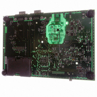
AT91RM3400-DK Atmel, AT91RM3400-DK Datasheet - Page 134

AT91RM3400-DK
Manufacturer Part Number
AT91RM3400-DK
Description
KIT DEV FOR AT91RM3400
Manufacturer
Atmel
Series
AT91SAM Smart ARMr
Type
MCUr
Datasheets
1.AT91RM3400-DK.pdf
(461 pages)
2.AT91RM3400-DK.pdf
(2 pages)
3.AT91RM3400-DK.pdf
(25 pages)
Specifications of AT91RM3400-DK
Contents
Evaluation Board, Software and Documentation
Processor To Be Evaluated
AT91RM3400
Data Bus Width
32 bit
Interface Type
RS-232, USB
For Use With/related Products
AT91RM3400
Lead Free Status / RoHS Status
Contains lead / RoHS non-compliant
- Current page: 134 of 461
- Download datasheet (6Mb)
Processor Clock Controller
Processor Clock Source
Idle Mode
134
AT91RM3400
prevents using the USB ports. Selecting the PLLB Clock saves the power consumption
of the PLLA by running the processor and the peripheral at 48 MHz required by the USB
ports. Selecting the PLLA Clock runs the processor and the peripherals at their maxi-
mum speed while running the USB ports at 48 MHz.
The Master Clock Controller is made up of a clock selector and a prescaler, as shown in
Figure 42. It also contains an optional Master Clock divider in products integrating an
ARM9 processor. This allows the processor clock to be faster than the Master Clock.
The Master Clock selection is made by writing the CSS field (Clock Source Selection) in
PMC_MCKR (Master Clock Register). The prescaler supports the division by a power of
2 of the selected clock between 1 and 64. The PRES field in PMC_MCKR programs the
prescaler.
When the Master Clock divider is implemented, it can be programmed between 1 and 4
through the MDIV field in PMC_MCKR.
Each time PMC_MCKR is written to define a new Master Clock, the MCKRDY bit is
cleared in PMC_SR. It reads 0 until the Master Clock is established. Then, the MCK-
RDY bit is set and can trigger an interrupt to the processor. This feature is useful when
switching from a high-speed clock to a lower one to inform the software when the
change is actually done.
Note:
Figure 42. Master Clock Controller
The PMC features a Processor Clock Controller that implements the Idle Mode. The
Processor Clock can be enabled and disabled by writing the System Clock Enable
(PMC_SCER) and System Clock Disable Registers (PMC_SCDR). The status of this
clock (at least for debug purpose) can be read in the System Clock Status Register
(PMC_SCSR).
The clock provided to the processor is determined by the Master Clock controller. On
ARM7-based systems, the Processor Clock source is directly the Master Clock.
On ARM9-based systems, the Processor Clock source might be 2, 3 or 4 times the Mas-
ter Clock. This ratio value is determined by programming the field MDIV of the Master
Clock Register (PMC_MCKR).
The Processor Clock is enabled after a reset and is automatically re-enabled by any
enabled interrupt. The Idle Mode is achieved by disabling the Processor Clock, which is
automatically re-enabled by any enabled fast or normal interrupt, or by the reset of the
product.
PLLA Clock
PLLB Clock
A new value to be written in PMC_MCKR must not be the same as the current value in
PMC_MCKR.
Main Clock
SLCK
CD
Master Clock
Prescaler
PRES
Master
Divider
Clock
MDIV
MCK
To the Processor
Clock Controller
To the Processor
Clock Controller
MCK
ARM9 Products
ARM7 Products
1790A–ATARM–11/03
Related parts for AT91RM3400-DK
Image
Part Number
Description
Manufacturer
Datasheet
Request
R

Part Number:
Description:
DEV KIT FOR AVR/AVR32
Manufacturer:
Atmel
Datasheet:

Part Number:
Description:
INTERVAL AND WIPE/WASH WIPER CONTROL IC WITH DELAY
Manufacturer:
ATMEL Corporation
Datasheet:

Part Number:
Description:
Low-Voltage Voice-Switched IC for Hands-Free Operation
Manufacturer:
ATMEL Corporation
Datasheet:

Part Number:
Description:
MONOLITHIC INTEGRATED FEATUREPHONE CIRCUIT
Manufacturer:
ATMEL Corporation
Datasheet:

Part Number:
Description:
AM-FM Receiver IC U4255BM-M
Manufacturer:
ATMEL Corporation
Datasheet:

Part Number:
Description:
Monolithic Integrated Feature Phone Circuit
Manufacturer:
ATMEL Corporation
Datasheet:

Part Number:
Description:
Multistandard Video-IF and Quasi Parallel Sound Processing
Manufacturer:
ATMEL Corporation
Datasheet:

Part Number:
Description:
High-performance EE PLD
Manufacturer:
ATMEL Corporation
Datasheet:

Part Number:
Description:
8-bit Flash Microcontroller
Manufacturer:
ATMEL Corporation
Datasheet:

Part Number:
Description:
2-Wire Serial EEPROM
Manufacturer:
ATMEL Corporation
Datasheet:


