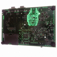
AT91RM3400-DK Atmel, AT91RM3400-DK Datasheet - Page 210

AT91RM3400-DK
Manufacturer Part Number
AT91RM3400-DK
Description
KIT DEV FOR AT91RM3400
Manufacturer
Atmel
Series
AT91SAM Smart ARMr
Type
MCUr
Datasheets
1.AT91RM3400-DK.pdf
(461 pages)
2.AT91RM3400-DK.pdf
(2 pages)
3.AT91RM3400-DK.pdf
(25 pages)
Specifications of AT91RM3400-DK
Contents
Evaluation Board, Software and Documentation
Processor To Be Evaluated
AT91RM3400
Data Bus Width
32 bit
Interface Type
RS-232, USB
For Use With/related Products
AT91RM3400
Lead Free Status / RoHS Status
Contains lead / RoHS non-compliant
- Current page: 210 of 461
- Download datasheet (6Mb)
Input Change
Interrupt
210
AT91RM3400
The PIO Controller can be programmed to generate an interrupt when it detects an input
change on an I/O line. The Input Change Interrupt is controlled by writing PIO_IER (Interrupt
Enable Register) and PIO_IDR (Interrupt Disable Register), which respectively enable and
disable the input change interrupt by setting and clearing the corresponding bit in PIO_IMR
(Interrupt Mask Register). As Input change detection is possible only by comparing two suc-
cessive samplings of the input of the I/O line, the PIO Controller clock must be enabled. The
Input Change Interrupt is available, regardless of the configuration of the I/O line, i.e. config-
ured as an input only, controlled by the PIO Controller or assigned to a peripheral function.
When an input change is detected on an I/O line, the corresponding bit in PIO_ISR (Interrupt
Status Register) is set. If the corresponding bit in PIO_IMR is set, the PIO Controller interrupt
line is asserted. The interrupt signals of the thirty-two channels are ORed-wired together to
generate a single interrupt signal to the Advanced Interrupt Controller.
When the software reads PIO_ISR, all the interrupts are automatically cleared. This signifies
that all the interrupts that are pending when PIO_ISR is read must be handled.
Figure 70. Input Change Interrupt Timings
Read PIO_ISR
PIO_PDSR
PIO_ISR
MCK
APB Access
APB Access
1790A–ATARM–11/03
Related parts for AT91RM3400-DK
Image
Part Number
Description
Manufacturer
Datasheet
Request
R

Part Number:
Description:
DEV KIT FOR AVR/AVR32
Manufacturer:
Atmel
Datasheet:

Part Number:
Description:
INTERVAL AND WIPE/WASH WIPER CONTROL IC WITH DELAY
Manufacturer:
ATMEL Corporation
Datasheet:

Part Number:
Description:
Low-Voltage Voice-Switched IC for Hands-Free Operation
Manufacturer:
ATMEL Corporation
Datasheet:

Part Number:
Description:
MONOLITHIC INTEGRATED FEATUREPHONE CIRCUIT
Manufacturer:
ATMEL Corporation
Datasheet:

Part Number:
Description:
AM-FM Receiver IC U4255BM-M
Manufacturer:
ATMEL Corporation
Datasheet:

Part Number:
Description:
Monolithic Integrated Feature Phone Circuit
Manufacturer:
ATMEL Corporation
Datasheet:

Part Number:
Description:
Multistandard Video-IF and Quasi Parallel Sound Processing
Manufacturer:
ATMEL Corporation
Datasheet:

Part Number:
Description:
High-performance EE PLD
Manufacturer:
ATMEL Corporation
Datasheet:

Part Number:
Description:
8-bit Flash Microcontroller
Manufacturer:
ATMEL Corporation
Datasheet:

Part Number:
Description:
2-Wire Serial EEPROM
Manufacturer:
ATMEL Corporation
Datasheet:


