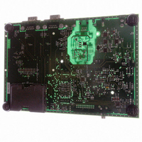
AT91RM3400-DK Atmel, AT91RM3400-DK Datasheet - Page 211

AT91RM3400-DK
Manufacturer Part Number
AT91RM3400-DK
Description
KIT DEV FOR AT91RM3400
Manufacturer
Atmel
Series
AT91SAM Smart ARMr
Type
MCUr
Datasheets
1.AT91RM3400-DK.pdf
(461 pages)
2.AT91RM3400-DK.pdf
(2 pages)
3.AT91RM3400-DK.pdf
(25 pages)
Specifications of AT91RM3400-DK
Contents
Evaluation Board, Software and Documentation
Processor To Be Evaluated
AT91RM3400
Data Bus Width
32 bit
Interface Type
RS-232, USB
For Use With/related Products
AT91RM3400
Lead Free Status / RoHS Status
Contains lead / RoHS non-compliant
- Current page: 211 of 461
- Download datasheet (6Mb)
I/O Lines
Programming
Example
1790A–ATARM–11/03
The programing example shown in Table 36 below is used to define the following
configuration.
•
•
•
•
•
•
•
Table 36. Programming Example
4-bit output port on I/O lines 0 to 3, (should be written in a single write operation), open-
drain, with pull-up resistor
Four output signals on I/O lines 4 to 7 (to drive LEDs for example), driven high and low, no
pull-up resistor
Four input signals on I/O lines 8 to 11 (to read push-button states for example), with pull-
up resistors, glitch filters and input change interrupts
Four input signals on I/O line 12 to 15 to read an external device status (polled, thus no
input change interrupt), no pull-up resistor, no glitch filter
I/O lines 16 to 19 assigned to peripheral A functions with pull-up resistor
I/O lines 20 to 23 assigned to peripheral B functions, no pull-up resistor
I/O lines 24 to 27 assigned to peripheral A with Input Change Interrupt and pull-up resistor
PIO_OWER
PIO_OWDR
PIO_CODR
PIO_MDER
PIO_MDDR
PIO_SODR
PIO_PUDR
PIO_PUER
PIO_IFER
PIO_IFDR
PIO_OER
PIO_ODR
PIO_PER
PIO_PDR
PIO_ASR
PIO_BSR
Register
PIO_IDR
PIO_IER
Value to be Written
0x0FFF F0FF
0x0FFF FFFF
0x0FFF FFF0
0x0FFF FFF0
0x0000 FFFF
0x0FFF FF00
0x00FF F0FF
0x0F0F FF0F
0x0FFF 0000
0x0000 00FF
0x0F00 0F00
0x00F0 00F0
0x0F0F 0000
0x0000 0F00
0x0000 0000
0x0000 000F
0x00F0 0000
0x0000 000F
AT91RM3400
211
Related parts for AT91RM3400-DK
Image
Part Number
Description
Manufacturer
Datasheet
Request
R

Part Number:
Description:
DEV KIT FOR AVR/AVR32
Manufacturer:
Atmel
Datasheet:

Part Number:
Description:
INTERVAL AND WIPE/WASH WIPER CONTROL IC WITH DELAY
Manufacturer:
ATMEL Corporation
Datasheet:

Part Number:
Description:
Low-Voltage Voice-Switched IC for Hands-Free Operation
Manufacturer:
ATMEL Corporation
Datasheet:

Part Number:
Description:
MONOLITHIC INTEGRATED FEATUREPHONE CIRCUIT
Manufacturer:
ATMEL Corporation
Datasheet:

Part Number:
Description:
AM-FM Receiver IC U4255BM-M
Manufacturer:
ATMEL Corporation
Datasheet:

Part Number:
Description:
Monolithic Integrated Feature Phone Circuit
Manufacturer:
ATMEL Corporation
Datasheet:

Part Number:
Description:
Multistandard Video-IF and Quasi Parallel Sound Processing
Manufacturer:
ATMEL Corporation
Datasheet:

Part Number:
Description:
High-performance EE PLD
Manufacturer:
ATMEL Corporation
Datasheet:

Part Number:
Description:
8-bit Flash Microcontroller
Manufacturer:
ATMEL Corporation
Datasheet:

Part Number:
Description:
2-Wire Serial EEPROM
Manufacturer:
ATMEL Corporation
Datasheet:


