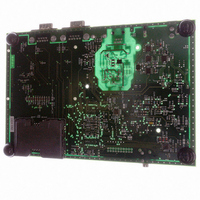
AT91RM3400-DK Atmel, AT91RM3400-DK Datasheet - Page 279

AT91RM3400-DK
Manufacturer Part Number
AT91RM3400-DK
Description
KIT DEV FOR AT91RM3400
Manufacturer
Atmel
Series
AT91SAM Smart ARMr
Type
MCUr
Datasheets
1.AT91RM3400-DK.pdf
(461 pages)
2.AT91RM3400-DK.pdf
(2 pages)
3.AT91RM3400-DK.pdf
(25 pages)
Specifications of AT91RM3400-DK
Contents
Evaluation Board, Software and Documentation
Processor To Be Evaluated
AT91RM3400
Data Bus Width
32 bit
Interface Type
RS-232, USB
For Use With/related Products
AT91RM3400
Lead Free Status / RoHS Status
Contains lead / RoHS non-compliant
- Current page: 279 of 461
- Download datasheet (6Mb)
Multi-drop Mode
1790A–ATARM–11/03
Table 48 shows an example of the parity bit for the character 0x41 (character ASCII “A”)
depending on the configuration of the USART. Because there are two bits at 1, 1 bit is added
when a parity is odd, or 0 is added when a parity is even. I
Table 48. Parity Bit Examples
When the receiver detects a parity error, it sets the PARE (Parity Error) bit in the Channel Sta-
tus Register (US_CSR). The PARE bit can be cleared by writing the Control Register (US_CR)
with the RSTSTA bit at 1. Figure 100 illustrates the parity bit status setting and clearing.
Figure 100. Parity Error
If the PAR field in the Mode Register (US_MR) is programmed to the value 0x3, the USART
runs in Multi-drop mode. This mode differentiates the data characters and the address charac-
ters. Data is transmitted with the parity bit at 0 and addresses are transmitted with the parity bit
at 1.
If the USART is configured in multi-drop mode, the receiver sets the PARE parity error bit
when the parity bit is high and the transmitter is able to send a character with the parity bit high
when the Control Register is written with the SENDA bit at 1.
To handle parity error, the PARE bit is cleared when the Control Register is written with the bit
RSTSTA at 1.
The transmitter sends an address byte (parity bit set) when SENDA is written to US_CR. In
this case, the next byte written to US_THR is transmitted as an address. Any character written
in US_THR without having written the command SENDA is transmitted normally with the parity
at 0.
Character
A
A
A
A
A
Baud Rate
RXRDY
US_CR
PARE
Clock
Write
RXD
Start
Bit
Hexa
0x41
0x41
0x41
0x41
0x41
D0
D1
D2
D3
D4
0100 0001
0100 0001
0100 0001
0100 0001
0100 0001
Binary
D5
D6
D7
Parity
Bad
Bit
Stop
Bit
Parity Bit
None
1
0
1
0
AT91RM3400
RSTSTA = 1
ParityMode
Space
None
Even
Mark
Odd
279
Related parts for AT91RM3400-DK
Image
Part Number
Description
Manufacturer
Datasheet
Request
R

Part Number:
Description:
DEV KIT FOR AVR/AVR32
Manufacturer:
Atmel
Datasheet:

Part Number:
Description:
INTERVAL AND WIPE/WASH WIPER CONTROL IC WITH DELAY
Manufacturer:
ATMEL Corporation
Datasheet:

Part Number:
Description:
Low-Voltage Voice-Switched IC for Hands-Free Operation
Manufacturer:
ATMEL Corporation
Datasheet:

Part Number:
Description:
MONOLITHIC INTEGRATED FEATUREPHONE CIRCUIT
Manufacturer:
ATMEL Corporation
Datasheet:

Part Number:
Description:
AM-FM Receiver IC U4255BM-M
Manufacturer:
ATMEL Corporation
Datasheet:

Part Number:
Description:
Monolithic Integrated Feature Phone Circuit
Manufacturer:
ATMEL Corporation
Datasheet:

Part Number:
Description:
Multistandard Video-IF and Quasi Parallel Sound Processing
Manufacturer:
ATMEL Corporation
Datasheet:

Part Number:
Description:
High-performance EE PLD
Manufacturer:
ATMEL Corporation
Datasheet:

Part Number:
Description:
8-bit Flash Microcontroller
Manufacturer:
ATMEL Corporation
Datasheet:

Part Number:
Description:
2-Wire Serial EEPROM
Manufacturer:
ATMEL Corporation
Datasheet:


