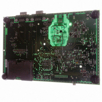
AT91RM3400-DK Atmel, AT91RM3400-DK Datasheet - Page 48

AT91RM3400-DK
Manufacturer Part Number
AT91RM3400-DK
Description
KIT DEV FOR AT91RM3400
Manufacturer
Atmel
Series
AT91SAM Smart ARMr
Type
MCUr
Datasheets
1.AT91RM3400-DK.pdf
(461 pages)
2.AT91RM3400-DK.pdf
(2 pages)
3.AT91RM3400-DK.pdf
(25 pages)
Specifications of AT91RM3400-DK
Contents
Evaluation Board, Software and Documentation
Processor To Be Evaluated
AT91RM3400
Data Bus Width
32 bit
Interface Type
RS-232, USB
For Use With/related Products
AT91RM3400
Lead Free Status / RoHS Status
Contains lead / RoHS non-compliant
- Current page: 48 of 461
- Download datasheet (6Mb)
Bootloader
Sequence
Device Initialization
Download Procedure
48
AT91RM3400
The Boot Program performs device initialization followed by the download procedure. If unsuc-
cessful, the upload is done via the USB or debug serial port.
Initialization follows the steps described below:
1. PLL setup
Table 13. Crystals Supported by Software Auto-detection (MHz)
2. Stacks setup for each ARM mode
3. Main oscillator frequency detection
4. Interrupt controller setup
5. C variables initialization
6. Branch main function
The download procedure checks for a valid boot on several devices. The first device checked
is a serial DataFlash connected to the NPCS0 of the SPI, followed by the serial EEPROM con-
nected to the TWI and by an 8-bit parallel memory connected on NCS0 of the External Bus
Interface (if EBI is implemented in the product).
3.0
4.433619
6.144
7.864320
12.0
16.0
25.0
–
PLLB is initialized to generate a 48 MHz clock necessary to use the USB Device. A
register located in the Power Management Controller (PMC) determines the
frequency of the main oscillator and thus the correct factor for the PLLB.
Table 13 defines the crystals supported by the Boot Program.
3.2768
4.9152
6.4
8.0
12.288
17.734470
28.224
3.6864
5.0
6.5536
9.8304
13.56
18.432
32.0
3.84
5.24288
7.159090
10.0
14.31818
20.0
33.0
4.0
6.0
7.3728
11.05920
14.7456
24.0
1790A–ATARM–11/03
Related parts for AT91RM3400-DK
Image
Part Number
Description
Manufacturer
Datasheet
Request
R

Part Number:
Description:
DEV KIT FOR AVR/AVR32
Manufacturer:
Atmel
Datasheet:

Part Number:
Description:
INTERVAL AND WIPE/WASH WIPER CONTROL IC WITH DELAY
Manufacturer:
ATMEL Corporation
Datasheet:

Part Number:
Description:
Low-Voltage Voice-Switched IC for Hands-Free Operation
Manufacturer:
ATMEL Corporation
Datasheet:

Part Number:
Description:
MONOLITHIC INTEGRATED FEATUREPHONE CIRCUIT
Manufacturer:
ATMEL Corporation
Datasheet:

Part Number:
Description:
AM-FM Receiver IC U4255BM-M
Manufacturer:
ATMEL Corporation
Datasheet:

Part Number:
Description:
Monolithic Integrated Feature Phone Circuit
Manufacturer:
ATMEL Corporation
Datasheet:

Part Number:
Description:
Multistandard Video-IF and Quasi Parallel Sound Processing
Manufacturer:
ATMEL Corporation
Datasheet:

Part Number:
Description:
High-performance EE PLD
Manufacturer:
ATMEL Corporation
Datasheet:

Part Number:
Description:
8-bit Flash Microcontroller
Manufacturer:
ATMEL Corporation
Datasheet:

Part Number:
Description:
2-Wire Serial EEPROM
Manufacturer:
ATMEL Corporation
Datasheet:


