C8051F020DK Silicon Laboratories Inc, C8051F020DK Datasheet - Page 6
C8051F020DK
Manufacturer Part Number
C8051F020DK
Description
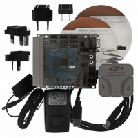
DEV KIT FOR F020/F021/F022/F023
Manufacturer
Silicon Laboratories Inc
Type
MCUr
Datasheet
1.C8051F020DK.pdf
(272 pages)
Specifications of C8051F020DK
Contents
Evaluation Board, Power Supply, USB Cables, Adapter and Documentation
Processor To Be Evaluated
C8051F02x
Interface Type
USB
Silicon Manufacturer
Silicon Labs
Core Architecture
8051
Silicon Core Number
C8051F020
Silicon Family Name
C8051F02x
Lead Free Status / RoHS Status
Contains lead / RoHS non-compliant
For Use With/related Products
Silicon Laboratories C8051 F020/021/022/023
Lead Free Status / Rohs Status
Lead free / RoHS Compliant
Other names
336-1200
Available stocks
Company
Part Number
Manufacturer
Quantity
Price
Company:

Part Number:
C8051F020DK
Manufacturer:
SiliconL
Quantity:
10


C8051F020/1/2/3
19. SERIAL PERIPHERAL INTERFACE BUS (SPI0) ........................................................197
20. UART0 ..................................................................................................................................205
21. UART1 ..................................................................................................................................215
22. TIMERS................................................................................................................................225
6
18.3.SMBus Transfer Modes.................................................................................................187
18.4.SMBus Special Function Registers ...............................................................................189
19.1.Signal Descriptions........................................................................................................198
19.2.SPI0 Operation ..............................................................................................................199
19.3.Serial Clock Timing ......................................................................................................200
19.4.SPI Special Function Registers .....................................................................................201
20.1.UART0 Operational Modes ..........................................................................................206
20.2.Multiprocessor Communications...................................................................................210
20.3.Frame and Transmission Error Detection......................................................................211
21.1.UART1 Operational Modes ..........................................................................................216
21.2.Multiprocessor Communications...................................................................................220
21.3.Frame and Transmission Error Detection......................................................................221
22.1.Timer 0 and Timer 1......................................................................................................227
22.2.Timer 2 .......................................................................................................................234
18.3.1. Master Transmitter Mode ....................................................................................187
18.3.2. Master Receiver Mode.........................................................................................187
18.3.3. Slave Transmitter Mode.......................................................................................188
18.3.4. Slave Receiver Mode ...........................................................................................188
18.4.1. Control Register ...................................................................................................189
18.4.2. Clock Rate Register .............................................................................................192
18.4.3. Data Register........................................................................................................193
18.4.4. Address Register ..................................................................................................193
18.4.5. Status Register .....................................................................................................194
19.1.1. Master Out, Slave In (MOSI) ..............................................................................198
19.1.2. Master In, Slave Out (MISO) ..............................................................................198
19.1.3. Serial Clock (SCK) ..............................................................................................198
19.1.4. Slave Select (NSS)...............................................................................................198
20.1.1. Mode 0: Synchronous Mode................................................................................206
20.1.2. Mode 1: 8-Bit UART, Variable Baud Rate .........................................................207
20.1.3. Mode 2: 9-Bit UART, Fixed Baud Rate ..............................................................208
20.1.4. Mode 3: 9-Bit UART, Variable Baud Rate .........................................................209
21.1.1. Mode 0: Synchronous Mode................................................................................216
21.1.2. Mode 1: 8-Bit UART, Variable Baud Rate .........................................................217
21.1.3. Mode 2: 9-Bit UART, Fixed Baud Rate ..............................................................218
21.1.4. Mode 3: 9-Bit UART, Variable Baud Rate .........................................................219
22.1.1. Mode 0: 13-bit Counter/Timer.............................................................................227
22.1.2. Mode 1: 16-bit Counter/Timer.............................................................................228
22.1.3. Mode 2: 8-bit Counter/Timer with Auto-Reload .................................................229
22.1.4. Mode 3: Two 8-bit Counter/Timers (Timer 0 Only) ...........................................230
22.2.1. Mode 0: 16-bit Counter/Timer with Capture .......................................................235
22.2.2. Mode 1: 16-bit Counter/Timer with Auto-Reload ...............................................236
Rev. 1.4
Related parts for C8051F020DK
Image
Part Number
Description
Manufacturer
Datasheet
Request
R

Part Number:
Description:
SMD/C°/SINGLE-ENDED OUTPUT SILICON OSCILLATOR
Manufacturer:
Silicon Laboratories Inc
Part Number:
Description:
Manufacturer:
Silicon Laboratories Inc
Datasheet:
Part Number:
Description:
N/A N/A/SI4010 AES KEYFOB DEMO WITH LCD RX
Manufacturer:
Silicon Laboratories Inc
Datasheet:
Part Number:
Description:
N/A N/A/SI4010 SIMPLIFIED KEY FOB DEMO WITH LED RX
Manufacturer:
Silicon Laboratories Inc
Datasheet:
Part Number:
Description:
N/A/-40 TO 85 OC/EZLINK MODULE; F930/4432 HIGH BAND (REV E/B1)
Manufacturer:
Silicon Laboratories Inc
Part Number:
Description:
EZLink Module; F930/4432 Low Band (rev e/B1)
Manufacturer:
Silicon Laboratories Inc
Part Number:
Description:
I°/4460 10 DBM RADIO TEST CARD 434 MHZ
Manufacturer:
Silicon Laboratories Inc
Part Number:
Description:
I°/4461 14 DBM RADIO TEST CARD 868 MHZ
Manufacturer:
Silicon Laboratories Inc
Part Number:
Description:
I°/4463 20 DBM RFSWITCH RADIO TEST CARD 460 MHZ
Manufacturer:
Silicon Laboratories Inc
Part Number:
Description:
I°/4463 20 DBM RADIO TEST CARD 868 MHZ
Manufacturer:
Silicon Laboratories Inc
Part Number:
Description:
I°/4463 27 DBM RADIO TEST CARD 868 MHZ
Manufacturer:
Silicon Laboratories Inc
Part Number:
Description:
I°/4463 SKYWORKS 30 DBM RADIO TEST CARD 915 MHZ
Manufacturer:
Silicon Laboratories Inc
Part Number:
Description:
N/A N/A/-40 TO 85 OC/4463 RFMD 30 DBM RADIO TEST CARD 915 MHZ
Manufacturer:
Silicon Laboratories Inc
Part Number:
Description:
I°/4463 20 DBM RADIO TEST CARD 169 MHZ
Manufacturer:
Silicon Laboratories Inc