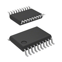
R5F21324CNSP#U0 Renesas Electronics America, R5F21324CNSP#U0 Datasheet - Page 21

R5F21324CNSP#U0
Manufacturer Part Number
R5F21324CNSP#U0
Description
MCU 1KB FLASH 16K ROM 20-LSSOP
Manufacturer
Renesas Electronics America
Series
R8C/3x/32Cr
Datasheet
1.R5F21321CDSPU0.pdf
(605 pages)
Specifications of R5F21324CNSP#U0
Core Processor
R8C
Core Size
16/32-Bit
Speed
20MHz
Connectivity
I²C, LIN, SIO, SSU, UART/USART
Peripherals
POR, PWM, Voltage Detect, WDT
Number Of I /o
15
Program Memory Size
16KB (16K x 8)
Program Memory Type
FLASH
Ram Size
1.5K x 8
Voltage - Supply (vcc/vdd)
1.8 V ~ 5.5 V
Data Converters
A/D 4x10b
Oscillator Type
Internal
Operating Temperature
-20°C ~ 85°C
Package / Case
20-LSSOP
Lead Free Status / RoHS Status
Lead free / RoHS Compliant
Eeprom Size
-
- Current page: 21 of 605
- Download datasheet (6Mb)
28.
29.
27.3
27.4
27.5
27.6
27.7
27.8
27.9
27.10
28.1
28.2
28.3
28.4
29.1
29.2
29.3
29.4
27.2.3
27.2.4
27.2.5
27.2.6
27.3.1
27.3.2
27.3.3
27.3.4
27.3.5
27.3.6
27.3.7
28.2.1
28.2.2
28.2.3
28.3.1
29.3.1
29.3.2
29.3.3
29.4.1
29.4.2
29.4.3
29.4.4
29.4.5
29.4.6
29.4.7
29.4.8
29.4.9
29.4.10 Data Protect Function ....................................................................................................................... 491
29.4.11 Software Commands ......................................................................................................................... 492
Comparator B ............................................................................................................................. 467
Flash Memory ............................................................................................................................. 474
Common Items for Multiple Modes ...................................................................................................... 451
One-Shot Mode ..................................................................................................................................... 457
Repeat Mode 0 ....................................................................................................................................... 458
Repeat Mode 1 ....................................................................................................................................... 459
Single Sweep Mode ............................................................................................................................... 461
Repeat Sweep Mode .............................................................................................................................. 463
Output Impedance of Sensor under A/D Conversion ............................................................................ 465
Notes on A/D Converter ........................................................................................................................ 466
Overview ............................................................................................................................................... 467
Registers ................................................................................................................................................ 469
Functional Description .......................................................................................................................... 471
Comparator B1 and Comparator B3 Interrupts ..................................................................................... 473
Overview ............................................................................................................................................... 474
Memory Map ......................................................................................................................................... 475
Functions to Prevent Flash Memory from being Rewritten .................................................................. 476
CPU Rewrite Mode ............................................................................................................................... 478
A/D Mode Register (ADMOD) ........................................................................................................ 447
A/D Input Select Register (ADINSEL) ............................................................................................ 448
A/D Control Register 0 (ADCON0) ................................................................................................. 449
A/D Control Register 1 (ADCON1) ................................................................................................. 450
Input/Output Pins .............................................................................................................................. 451
A/D Conversion Cycles .................................................................................................................... 451
A/D Conversion Start Condition ....................................................................................................... 453
A/D Conversion Result ..................................................................................................................... 455
Low Current Consumption Function ................................................................................................ 455
Extended Analog Input Pins ............................................................................................................. 455
A/D Open-Circuit Detection Assist Function ................................................................................... 455
Comparator B Control Register (INTCMP) ..................................................................................... 469
External Input Enable Register 0 (INTEN) ...................................................................................... 469
INT Input Filter Select Register 0 (INTF) ........................................................................................ 470
Comparator Bi Digital Filter (i = 1 or 3) .......................................................................................... 472
ID Code Check Function .................................................................................................................. 476
ROM Code Protect Function ............................................................................................................ 477
Option Function Select Register (OFS) ............................................................................................ 477
Flash Memory Status Register (FST) ............................................................................................... 479
Flash Memory Control Register 0 (FMR0) ...................................................................................... 481
Flash Memory Control Register 1 (FMR1) ...................................................................................... 483
Flash Memory Control Register 2 (FMR2) ...................................................................................... 485
EW0 Mode ........................................................................................................................................ 487
EW1 Mode ........................................................................................................................................ 487
Suspend Operation ............................................................................................................................ 488
How to Set and Exit Each Mode ....................................................................................................... 489
BGO (BackGround Operation) Function .......................................................................................... 490
A - 12
Related parts for R5F21324CNSP#U0
Image
Part Number
Description
Manufacturer
Datasheet
Request
R

Part Number:
Description:
KIT STARTER FOR M16C/29
Manufacturer:
Renesas Electronics America
Datasheet:

Part Number:
Description:
KIT STARTER FOR R8C/2D
Manufacturer:
Renesas Electronics America
Datasheet:

Part Number:
Description:
R0K33062P STARTER KIT
Manufacturer:
Renesas Electronics America
Datasheet:

Part Number:
Description:
KIT STARTER FOR R8C/23 E8A
Manufacturer:
Renesas Electronics America
Datasheet:

Part Number:
Description:
KIT STARTER FOR R8C/25
Manufacturer:
Renesas Electronics America
Datasheet:

Part Number:
Description:
KIT STARTER H8S2456 SHARPE DSPLY
Manufacturer:
Renesas Electronics America
Datasheet:

Part Number:
Description:
KIT STARTER FOR R8C38C
Manufacturer:
Renesas Electronics America
Datasheet:

Part Number:
Description:
KIT STARTER FOR R8C35C
Manufacturer:
Renesas Electronics America
Datasheet:

Part Number:
Description:
KIT STARTER FOR R8CL3AC+LCD APPS
Manufacturer:
Renesas Electronics America
Datasheet:

Part Number:
Description:
KIT STARTER FOR RX610
Manufacturer:
Renesas Electronics America
Datasheet:

Part Number:
Description:
KIT STARTER FOR R32C/118
Manufacturer:
Renesas Electronics America
Datasheet:

Part Number:
Description:
KIT DEV RSK-R8C/26-29
Manufacturer:
Renesas Electronics America
Datasheet:

Part Number:
Description:
KIT STARTER FOR SH7124
Manufacturer:
Renesas Electronics America
Datasheet:

Part Number:
Description:
KIT STARTER FOR H8SX/1622
Manufacturer:
Renesas Electronics America
Datasheet:

Part Number:
Description:
KIT DEV FOR SH7203
Manufacturer:
Renesas Electronics America
Datasheet:


