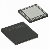
ATMEGA324P-A15MZ Atmel, ATMEGA324P-A15MZ Datasheet - Page 275

ATMEGA324P-A15MZ
Manufacturer Part Number
ATMEGA324P-A15MZ
Description
MCU AVR 32KB FLASH 15MHZ 44-VQFN
Manufacturer
Atmel
Series
AVR® ATmegar
Datasheet
1.ATMEGA324P-A15MZ.pdf
(346 pages)
Specifications of ATMEGA324P-A15MZ
Package / Case
44-VQFN Exposed Pad
Voltage - Supply (vcc/vdd)
2.7 V ~ 5.5 V
Operating Temperature
-40°C ~ 125°C
Speed
16MHz
Number Of I /o
32
Eeprom Size
1K x 8
Core Processor
AVR
Program Memory Type
FLASH
Ram Size
2K x 8
Program Memory Size
32KB (32K x 8)
Data Converters
A/D 8x10b
Oscillator Type
Internal
Peripherals
Brown-out Detect/Reset, POR, PWM, WDT
Connectivity
I²C, SPI, UART/USART
Core Size
8-Bit
Lead Free Status / RoHS Status
Lead free / RoHS Compliant
- Current page: 275 of 346
- Download datasheet (3Mb)
AVR_RESET ($C)
PROG_ENABLE ($4)
2503N–AVR–06/08
Figure 138. State Machine Sequence for Changing the Instruction Word
The AVR specific public JTAG instruction for setting the AVR device in the Reset mode or taking
the device out from the Reset Mode. The TAP controller is not reset by this instruction. The one
bit Reset Register is selected as Data Register. Note that the Reset will be active as long as
there is a logic “one” in the Reset Chain. The output from this chain is not latched.
The active states are:
•
The AVR specific public JTAG instruction for enabling programming via the JTAG port. The 16-
bit Programming Enable Register is selected as Data Register. The active states are the
following:
•
•
Shift-DR: The Reset Register is shifted by the TCK input.
Shift-DR: The programming enable signature is shifted into the Data Register.
Update-DR: The programming enable signature is compared to the correct value, and
Programming mode is entered if the signature is valid.
1
0
Test-Logic-Reset
Run-Test/Idle
0
1
1
0
Select-DR Scan
Capture-DR
Update-DR
Pause-DR
Exit1-DR
Exit2-DR
Shift-DR
1
0
0
1
0
1
1
0
1
1
0
0
1
0
Select-IR Scan
Capture-IR
ATmega32(L)
Update-IR
Pause-IR
Exit1-IR
Exit2-IR
Shift-IR
1
0
0
1
0
1
1
0
1
1
0
0
275
Related parts for ATMEGA324P-A15MZ
Image
Part Number
Description
Manufacturer
Datasheet
Request
R

Part Number:
Description:
Manufacturer:
Atmel Corporation
Datasheet:

Part Number:
Description:
Manufacturer:
Atmel Corporation
Datasheet:

Part Number:
Description:
IC MCU AVR 32K FLASH 44-TQFP
Manufacturer:
Atmel
Datasheet:

Part Number:
Description:
IC MCU AVR 32K FLASH 44-QFN
Manufacturer:
Atmel
Datasheet:

Part Number:
Description:
IC MCU AVR 32K FLASH 40-DIP
Manufacturer:
Atmel
Datasheet:

Part Number:
Description:
MCU AVR 32K FLASH 20MHZ 44-QFN
Manufacturer:
Atmel
Datasheet:

Part Number:
Description:
MCU AVR 32KB FLASH 20MHZ 44TQFP
Manufacturer:
Atmel
Datasheet:

Part Number:
Description:
MCU AVR 32KB FLASH 20MHZ 44QFN
Manufacturer:
Atmel
Datasheet:

Part Number:
Description:
MCU AVR 32KB FLASH 20MHZ 44TQFP
Manufacturer:
Atmel
Datasheet:

Part Number:
Description:
MCU AVR 32K FLASH 20MHZ 44-QFN
Manufacturer:
Atmel
Datasheet:

Part Number:
Description:
MCU AVR 32K FLASH 15MHZ 44-TQFP
Manufacturer:
Atmel
Datasheet:


