HD6417750SBP200 Renesas Electronics America, HD6417750SBP200 Datasheet - Page 295
HD6417750SBP200
Manufacturer Part Number
HD6417750SBP200
Description
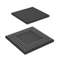
IC SUPERH MPU ROMLESS 256BGA
Manufacturer
Renesas Electronics America
Series
SuperH® SH7750r
Datasheet
1.D6417750RBP240DV.pdf
(1164 pages)
Specifications of HD6417750SBP200
Core Processor
SH-4
Core Size
32-Bit
Speed
200MHz
Connectivity
EBI/EMI, FIFO, SCI, SmartCard
Peripherals
DMA, POR, WDT
Number Of I /o
28
Program Memory Type
ROMless
Ram Size
24K x 8
Voltage - Supply (vcc/vdd)
1.8 V ~ 2.07 V
Oscillator Type
External
Operating Temperature
-20°C ~ 75°C
Package / Case
256-BGA
Lead Free Status / RoHS Status
Contains lead / RoHS non-compliant
Eeprom Size
-
Program Memory Size
-
Data Converters
-
Available stocks
Company
Part Number
Manufacturer
Quantity
Price

Part Number:
HD6417750SBP200
Manufacturer:
RENESAS/瑞萨
Quantity:
20 000


7.1
PC: At the start of instruction execution, PC indicates the address of the instruction itself.
Data sizes and data types: The SH-4's instruction set is implemented with 16-bit fixed-length
instructions. The SH-4 can use byte (8-bit), word (16-bit), longword (32-bit), and quadword (64-
bit) data sizes for memory access. Single-precision floating-point data (32 bits) can be moved to
and from memory using longword or quadword size. Double-precision floating-point data (64 bits)
can be moved to and from memory using longword size. When a double-precision floating-point
operation is specified (FPSCR.PR = 1), the result of an operation using quadword access will be
undefined. When the SH-4 moves byte-size or word-size data from memory to a register, the data
is sign-extended.
Load-Store Architecture: The SH-4 features a load-store architecture in which operations are
basically executed using registers. Except for bit-manipulation operations such as logical AND
that are executed directly in memory, operands in an operation that requires memory access are
loaded into registers and the operation is executed between the registers.
Delayed Branches: Except for the two branch instructions BF and BT, the SH-4's branch
instructions and RTE are delayed branches. In a delayed branch, the instruction following the
branch is executed before the branch destination instruction. This execution slot following a
delayed branch is called a delay slot. For example, the BRA execution sequence is as follows:
Static Sequence
BRA
ADD
next_2
Delay Slot: An illegal instruction exception may occur when a specific instruction is executed in a
delay slot. See section 5, Exceptions. The instruction following BF/S or BT/S for which the
branch is not taken is also a delay slot instruction.
T Bit: The T bit in the status register (SR) is used to show the result of a compare operation, and
is referenced by a conditional branch instruction. An example of the use of a conditional branch
instruction is shown below.
TARGET
R1, R0
Execution Environment
Section 7 Instruction Set
Dynamic Sequence
BRA
ADD
target_instr
TARGET
R1, R0
Rev.7.00 Oct. 10, 2008 Page 209 of 1074
ADD in delay slot is executed before
branching to TARGET
Section 7 Instruction Set
REJ09B0366-0700
Related parts for HD6417750SBP200
Image
Part Number
Description
Manufacturer
Datasheet
Request
R

Part Number:
Description:
KIT STARTER FOR M16C/29
Manufacturer:
Renesas Electronics America
Datasheet:

Part Number:
Description:
KIT STARTER FOR R8C/2D
Manufacturer:
Renesas Electronics America
Datasheet:

Part Number:
Description:
R0K33062P STARTER KIT
Manufacturer:
Renesas Electronics America
Datasheet:

Part Number:
Description:
KIT STARTER FOR R8C/23 E8A
Manufacturer:
Renesas Electronics America
Datasheet:

Part Number:
Description:
KIT STARTER FOR R8C/25
Manufacturer:
Renesas Electronics America
Datasheet:

Part Number:
Description:
KIT STARTER H8S2456 SHARPE DSPLY
Manufacturer:
Renesas Electronics America
Datasheet:

Part Number:
Description:
KIT STARTER FOR R8C38C
Manufacturer:
Renesas Electronics America
Datasheet:

Part Number:
Description:
KIT STARTER FOR R8C35C
Manufacturer:
Renesas Electronics America
Datasheet:

Part Number:
Description:
KIT STARTER FOR R8CL3AC+LCD APPS
Manufacturer:
Renesas Electronics America
Datasheet:
Part Number:
Description:
KIT STARTER FOR RX610
Manufacturer:
Renesas Electronics America
Datasheet:

Part Number:
Description:
KIT STARTER FOR R32C/118
Manufacturer:
Renesas Electronics America
Datasheet:

Part Number:
Description:
KIT DEV RSK-R8C/26-29
Manufacturer:
Renesas Electronics America
Datasheet:

Part Number:
Description:
KIT STARTER FOR SH7124
Manufacturer:
Renesas Electronics America
Datasheet:

Part Number:
Description:
KIT STARTER FOR H8SX/1622
Manufacturer:
Renesas Electronics America
Datasheet:

Part Number:
Description:
KIT DEV FOR SH7203
Manufacturer:
Renesas Electronics America
Datasheet: