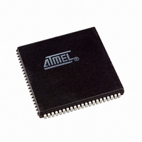
AT94K05AL-25AJI Atmel, AT94K05AL-25AJI Datasheet - Page 101

AT94K05AL-25AJI
Manufacturer Part Number
AT94K05AL-25AJI
Description
IC FPSLIC 5K GATE 25MHZ 84PLCC
Manufacturer
Atmel
Series
FPSLIC®r
Specifications of AT94K05AL-25AJI
Core Type
8-bit AVR
Speed
25MHz
Interface
I²C, UART
Program Sram Bytes
4K-16K
Fpga Sram
2kb
Data Sram Bytes
4K ~ 16K
Fpga Core Cells
256
Fpga Gates
5K
Fpga Registers
436
Voltage - Supply
3 V ~ 3.6 V
Mounting Type
Surface Mount
Operating Temperature
-40°C ~ 85°C
Package / Case
84-PLCC
For Use With
ATSTK594 - BOARD FPSLIC DAUGHTER FOR STK500
Lead Free Status / RoHS Status
Contains lead / RoHS non-compliant
Eeprom Size
-
Available stocks
Company
Part Number
Manufacturer
Quantity
Price
- Current page: 101 of 204
- Download datasheet (4Mb)
4.26
Figure 4-31. Timer/Counter1 Block Diagram
1138I–FPSLI–1/08
Timer/Counter1
REGISTER (TIMSK)
15
15
15
15
TIMER INT. MASK
TIMER/COUNTER1 OUTPUT COMPARE REGISTER A
T/C1 OVER-
T/C1 INPUT CAPTURE REGISTER (ICR1)
FLOW IRQ
TIMER/COUNTER1 (TCNT1)
16 BIT COMPARATOR
Figure 4-31
The 16-bit Timer/Counter1 can select the clock source from CK, prescaled CK, or an external
pin. In addition it can be stopped as described in section
TCCR1B” on page
are found in the Timer/Counter Interrupt Flag Register – TIFR. Control signals are found in the
Timer/Counter1 Control Registers – TCCR1A and TCCR1B. The interrupt enable/disable set-
tings for Timer/Counter1 are found in the Timer/Counter Interrupt Mask Register – TIMSK.
When Timer/Counter1 is externally clocked, the external signal is synchronized with the oscilla-
tor frequency of the CPU. To assure proper sampling of the external clock, the minimum time
between two external clock transitions must be at least one internal CPU clock period. The
external clock signal is sampled on the rising edge of the internal CPU clock.
The 16-bit Timer/Counter1 features both a high-resolution and a high-accuracy usage with the
lower prescaling opportunities. Similarly, the high-prescaling opportunities makes the
T/C1 COMPARE
8
MATCHA IRQ
8
8
8
7
7
7
7
TIMER INT. FLAG
REGISTER (TIFR)
shows the block diagram for Timer/Counter1.
T/C1 COMPARE
MATCHB IRQ
104. The different status flags (overflow, compare match and capture event)
CAPTURE
TRIGGER
0
0
0
0
REGISTER A (TCCR1A)
15
15
TIMER/COUNTER1 OUTPUT COMPARE REGISTER B
T/C CLEAR
T/C CLOCK SOURCE
UP/DOWN
T/C1 CONTROL
CAPTURE IRQ
T/C1 INPUT
16 BIT COMPARATOR
CONTROL
AT94KAL Series FPSLIC
LOGIC
8
8
7
7
REGISTER B (TCCR1B)
T/C1 CONTROL
“Timer/Counter1 Control Register B –
0
0
SPECIAL FUNCTIONS
IO REGISTER (SFIOR)
T1
CK
101
Related parts for AT94K05AL-25AJI
Image
Part Number
Description
Manufacturer
Datasheet
Request
R

Part Number:
Description:
IC FPSLIC 5K GATE 25MHZ 84PLCC
Manufacturer:
Atmel
Datasheet:

Part Number:
Description:
Fpslic Devices Combine 5K Gates of Atmel's Patented AT40K Fpga Architecture, a 20 Mips Avr 8-bit Risc Microprocessor Core, Numerous Fixed Microcontroller Peripheries And up to 36K Bytes of Program And Data SRAM.
Manufacturer:
ATMEL Corporation
Datasheet:

Part Number:
Description:
IC FPSLIC 5K GATE 25MHZ 208PQFP
Manufacturer:
Atmel
Datasheet:

Part Number:
Description:
IC FPSLIC 5K GATE 25MHZ 144LQFP
Manufacturer:
Atmel
Datasheet:

Part Number:
Description:
IC FPSLIC 5K GATE 25MHZ 208PQFP
Manufacturer:
Atmel
Datasheet:

Part Number:
Description:
IC FPSLIC 5K GATE 25MHZ 144LQFP
Manufacturer:
Atmel
Datasheet:

Part Number:
Description:
IC FPSLIC 5K GATE 25MHZ 144-LQFP
Manufacturer:
Atmel
Datasheet:

Part Number:
Description:
IC FPSLIC 5K GATE 25MHZ 100-TQFP
Manufacturer:
Atmel
Datasheet:

Part Number:
Description:
Manufacturer:
Atmel
Datasheet:

Part Number:
Description:
Manufacturer:
Atmel
Datasheet:

Part Number:
Description:
Manufacturer:
Atmel
Datasheet:

Part Number:
Description:
5k - 40k Gates Of At40k Fpga With 8-bit Microcontroller, Up To 36k Bytes Of Sram And On-chip Jtag Ice
Manufacturer:
ATMEL Corporation
Datasheet:

Part Number:
Description:
At94k05al 5k - 40k Gates Of At40k Fpga With 8-bit Microcontroller, Up To 36k Bytes Of Sram And On-chip Jtag Ice
Manufacturer:
ATMEL Corporation
Datasheet:

Part Number:
Description:
DEV KIT FOR AVR/AVR32
Manufacturer:
Atmel
Datasheet:


