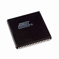
AT94K05AL-25AJI Atmel, AT94K05AL-25AJI Datasheet - Page 140

AT94K05AL-25AJI
Manufacturer Part Number
AT94K05AL-25AJI
Description
IC FPSLIC 5K GATE 25MHZ 84PLCC
Manufacturer
Atmel
Series
FPSLIC®r
Specifications of AT94K05AL-25AJI
Core Type
8-bit AVR
Speed
25MHz
Interface
I²C, UART
Program Sram Bytes
4K-16K
Fpga Sram
2kb
Data Sram Bytes
4K ~ 16K
Fpga Core Cells
256
Fpga Gates
5K
Fpga Registers
436
Voltage - Supply
3 V ~ 3.6 V
Mounting Type
Surface Mount
Operating Temperature
-40°C ~ 85°C
Package / Case
84-PLCC
For Use With
ATSTK594 - BOARD FPSLIC DAUGHTER FOR STK500
Lead Free Status / RoHS Status
Contains lead / RoHS non-compliant
Eeprom Size
-
Available stocks
Company
Part Number
Manufacturer
Quantity
Price
- Current page: 140 of 204
- Download datasheet (4Mb)
4.30
140
2-wire Serial Interface (Byte Oriented)
AT94KAL Series FPSLIC
The 2-wire Serial Bus is a bi-directional two-wire serial communication standard. It is designed
primarily for simple but efficient integrated circuit (IC) control. The system is comprised of two
lines, SCL (Serial Clock) and SDA (Serial Data) that carry information between the ICs con-
nected to them. Various communication configurations can be designed using this bus.
Figure 4-45
can be Master or Slave.
Figure 4-45. 2-wire Serial Bus Configuration
The 2-wire Serial Interface provides a serial interface that meets the 2-wire Serial Bus specifica-
tion and supports Master/Slave and Transmitter/Receiver operation at up to 400 kHz bus clock
rate. The 2-wire Serial Interface has hardware support for the 7-bit addressing, but is easily
extended to 10-bit addressing format in software. When operating in 2-wire Serial mode, i.e.,
when TWEN is set, a glitch filter is enabled for the input signals from the pins SCL and SDA, and
the output from these pins are slew-rate controlled. The 2-wire Serial Interface is byte oriented.
The operation of the serial 2-wire Serial Bus is shown as a pulse diagram in
ing the START and STOP conditions and generation of ACK signal by the bus receiver.
Figure 4-46. 2-wire Serial Bus Timing Diagram
The block diagram of the 2-wire Serial Bus interface is shown in
SDA
SCL
CONDITION
START
shows a typical 2-wire Serial Bus configuration. Any device connected to the bus
MSB
Device 1
1
2
Device 2
7
R/W
BIT
8
Device 3
ACK
9
FROM RECEIVER
ACKNOWLEDGE
.......
1
2
Device n
Figure
8
REPEATED START CONDITION
R1
4-47.
ACK
9
R2
Figure
STOP CONDITION
1138I–FPSLI–1/08
4-46, includ-
V
SCL
SDA
CC
Related parts for AT94K05AL-25AJI
Image
Part Number
Description
Manufacturer
Datasheet
Request
R

Part Number:
Description:
IC FPSLIC 5K GATE 25MHZ 84PLCC
Manufacturer:
Atmel
Datasheet:

Part Number:
Description:
Fpslic Devices Combine 5K Gates of Atmel's Patented AT40K Fpga Architecture, a 20 Mips Avr 8-bit Risc Microprocessor Core, Numerous Fixed Microcontroller Peripheries And up to 36K Bytes of Program And Data SRAM.
Manufacturer:
ATMEL Corporation
Datasheet:

Part Number:
Description:
IC FPSLIC 5K GATE 25MHZ 208PQFP
Manufacturer:
Atmel
Datasheet:

Part Number:
Description:
IC FPSLIC 5K GATE 25MHZ 144LQFP
Manufacturer:
Atmel
Datasheet:

Part Number:
Description:
IC FPSLIC 5K GATE 25MHZ 208PQFP
Manufacturer:
Atmel
Datasheet:

Part Number:
Description:
IC FPSLIC 5K GATE 25MHZ 144LQFP
Manufacturer:
Atmel
Datasheet:

Part Number:
Description:
IC FPSLIC 5K GATE 25MHZ 144-LQFP
Manufacturer:
Atmel
Datasheet:

Part Number:
Description:
IC FPSLIC 5K GATE 25MHZ 100-TQFP
Manufacturer:
Atmel
Datasheet:

Part Number:
Description:
Manufacturer:
Atmel
Datasheet:

Part Number:
Description:
Manufacturer:
Atmel
Datasheet:

Part Number:
Description:
Manufacturer:
Atmel
Datasheet:

Part Number:
Description:
5k - 40k Gates Of At40k Fpga With 8-bit Microcontroller, Up To 36k Bytes Of Sram And On-chip Jtag Ice
Manufacturer:
ATMEL Corporation
Datasheet:

Part Number:
Description:
At94k05al 5k - 40k Gates Of At40k Fpga With 8-bit Microcontroller, Up To 36k Bytes Of Sram And On-chip Jtag Ice
Manufacturer:
ATMEL Corporation
Datasheet:

Part Number:
Description:
DEV KIT FOR AVR/AVR32
Manufacturer:
Atmel
Datasheet:


