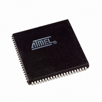
AT94K05AL-25AJI Atmel, AT94K05AL-25AJI Datasheet - Page 32

AT94K05AL-25AJI
Manufacturer Part Number
AT94K05AL-25AJI
Description
IC FPSLIC 5K GATE 25MHZ 84PLCC
Manufacturer
Atmel
Series
FPSLIC®r
Specifications of AT94K05AL-25AJI
Core Type
8-bit AVR
Speed
25MHz
Interface
I²C, UART
Program Sram Bytes
4K-16K
Fpga Sram
2kb
Data Sram Bytes
4K ~ 16K
Fpga Core Cells
256
Fpga Gates
5K
Fpga Registers
436
Voltage - Supply
3 V ~ 3.6 V
Mounting Type
Surface Mount
Operating Temperature
-40°C ~ 85°C
Package / Case
84-PLCC
For Use With
ATSTK594 - BOARD FPSLIC DAUGHTER FOR STK500
Lead Free Status / RoHS Status
Contains lead / RoHS non-compliant
Eeprom Size
-
Available stocks
Company
Part Number
Manufacturer
Quantity
Price
- Current page: 32 of 204
- Download datasheet (4Mb)
32
AT94KAL Series FPSLIC
Table 3-7.
Bit
SCR31
SCR32 - SCR34
SCR35
SCR36
SCR37
SCR38
SCR39
SCR40 - SCR41
SCR 42 -
SCR47
SCR48
SCR49
SCR50
SCR51
SCR52
SCR53
FPSLIC System Control Register (Continued)
Description
0 = Disable I/O Tri-state
1 = I/O Tri-state During (Internal and External) Configuration Download.
SCR31 forces all user defined I/O pins to go tri-state during configuration
download. Tri-state is released at the end of configuration download on the rising
edge of CON, if set.
Reserved
0 = AVR Reset Pin Disabled
1 = AVR Reset Pin Enabled (active Low Reset)
SCR35 allows the AVR Reset pin to reset the AVR only.
0 = Protect AVR Program SRAM
1 = Allow Writes to AVR Program SRAM (Excluding Boot Block)
SCR36 protects AVR program code from writes by the FPGA.
0 = AVR Program SRAM Boot Block Protect
1 = AVR Program SRAM Boot Block Allows Overwrite
0 = (default) Frame Clock Inverted to AVR Data/Program SRAM
1 = Non-inverting Clock Into AVR Data/Program SRAM
Reserved
SCR41 = 0, SCR40 = 0 16 Kbytes x 16 Program/4 Kbytes x 8 Data
SCR41 = 0, SCR40 = 1 14 Kbytes x 16 Program/8 Kbytes x 8 Data
SCR41 = 1, SCR40 = 0 12 Kbytes x 16 Program/12 Kbytes x 8 Data
SCR41 = 1, SCR40 = 1 10 Kbytes x 16 Program/16 Kbytes x 8 Data
SCR40 : SCR41 AVR program/data SRAM partitioning (set by using the AT94K
Device Options in System Designer).
Reserved
0 = EXT-INT0 Driven By Port E<4>
1 = EXT-INT0 Driven By INTP0 pad
SCR48 : SCR53 Defaults dependent on package selected.
0 = EXT-INT1 Driven By Port E<5>
1 = EXT-INT1 Driven By INTP1 pad
SCR48 : SCR53 Defaults dependent on package selected.
0 = EXT-INT2 Driven By Port E<6>
1 = EXT-INT2 Driven By INTP2 pad
SCR48 : SCR53 Defaults dependent on package selected.
0 = EXT-INT3 Driven By Port E<7>
1 = EXT-INT3 Driven By INTP3 pad
SCR48 : SCR53 Defaults dependent on package selected.
0 = UART0 Pins Assigned to Port E<1:0>
1 = UART0 Pins Assigned to UART0 pads
SCR48 : SCR53 Defaults dependent on package selected.
0 = UART1 Pins Assigned to Port E<3:2>
1 = UART1 Pins Assigned to UART1 pads
SCR48 : SCR53 Defaults dependent on package selected.
On packages less than 144-pins, there is reduced access to AVR ports. Port D is
not available externally in the smallest package and Port E becomes dual-purpose
I/O to maintain access to the UARTs and external interrupt pins. The Pin List (East
Side) on
page 188
shows exactly which pins are available in each package.
1138I–FPSLI–1/08
Related parts for AT94K05AL-25AJI
Image
Part Number
Description
Manufacturer
Datasheet
Request
R

Part Number:
Description:
IC FPSLIC 5K GATE 25MHZ 84PLCC
Manufacturer:
Atmel
Datasheet:

Part Number:
Description:
Fpslic Devices Combine 5K Gates of Atmel's Patented AT40K Fpga Architecture, a 20 Mips Avr 8-bit Risc Microprocessor Core, Numerous Fixed Microcontroller Peripheries And up to 36K Bytes of Program And Data SRAM.
Manufacturer:
ATMEL Corporation
Datasheet:

Part Number:
Description:
IC FPSLIC 5K GATE 25MHZ 208PQFP
Manufacturer:
Atmel
Datasheet:

Part Number:
Description:
IC FPSLIC 5K GATE 25MHZ 144LQFP
Manufacturer:
Atmel
Datasheet:

Part Number:
Description:
IC FPSLIC 5K GATE 25MHZ 208PQFP
Manufacturer:
Atmel
Datasheet:

Part Number:
Description:
IC FPSLIC 5K GATE 25MHZ 144LQFP
Manufacturer:
Atmel
Datasheet:

Part Number:
Description:
IC FPSLIC 5K GATE 25MHZ 144-LQFP
Manufacturer:
Atmel
Datasheet:

Part Number:
Description:
IC FPSLIC 5K GATE 25MHZ 100-TQFP
Manufacturer:
Atmel
Datasheet:

Part Number:
Description:
Manufacturer:
Atmel
Datasheet:

Part Number:
Description:
Manufacturer:
Atmel
Datasheet:

Part Number:
Description:
Manufacturer:
Atmel
Datasheet:

Part Number:
Description:
5k - 40k Gates Of At40k Fpga With 8-bit Microcontroller, Up To 36k Bytes Of Sram And On-chip Jtag Ice
Manufacturer:
ATMEL Corporation
Datasheet:

Part Number:
Description:
At94k05al 5k - 40k Gates Of At40k Fpga With 8-bit Microcontroller, Up To 36k Bytes Of Sram And On-chip Jtag Ice
Manufacturer:
ATMEL Corporation
Datasheet:

Part Number:
Description:
DEV KIT FOR AVR/AVR32
Manufacturer:
Atmel
Datasheet:


