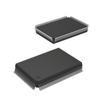
DF2357F20 Renesas Electronics America, DF2357F20 Datasheet - Page 508

DF2357F20
Manufacturer Part Number
DF2357F20
Description
IC H8S MCU FLASH 5V 128K 128QFP
Manufacturer
Renesas Electronics America
Series
H8® H8S/2300r
Datasheet
1.D12392F20V.pdf
(1049 pages)
Specifications of DF2357F20
Core Processor
H8S/2000
Core Size
16-Bit
Speed
20MHz
Connectivity
SCI, SmartCard
Peripherals
DMA, POR, PWM, WDT
Number Of I /o
87
Program Memory Size
128KB (128K x 8)
Program Memory Type
FLASH
Ram Size
8K x 8
Voltage - Supply (vcc/vdd)
4.5 V ~ 5.5 V
Data Converters
A/D 8x10b; D/A 2x8b
Oscillator Type
Internal
Operating Temperature
-20°C ~ 75°C
Package / Case
128-QFP
Lead Free Status / RoHS Status
Contains lead / RoHS non-compliant
Eeprom Size
-
Available stocks
Company
Part Number
Manufacturer
Quantity
Price
Company:
Part Number:
DF2357F20
Manufacturer:
Renesas Electronics America
Quantity:
10 000
Company:
Part Number:
DF2357F20IV
Manufacturer:
Renesas Electronics America
Quantity:
10 000
- Current page: 508 of 1049
- Download datasheet (5Mb)
Bit 0—Multiprocessor Bit Transfer (MPBT): When transmission is performed using multiprocessor format in
asynchronous mode, MPBT stores the multiprocessor bit to be added to the transmit data.
The MPBT bit setting is invalid when multiprocessor format is not used, when not transmitting, and in clocked
synchronous mode.
14.2.8
BRR is an 8-bit register that sets the serial transfer bit rate in accordance with the baud rate generator operating clock
selected by bits CKS1 and CKS0 in SMR.
BRR can be read or written to by the CPU at all times.
BRR is initialized to H'FF by a reset, and by putting the device in standby mode or module stop mode. In the H8S/2398,
H8S/2394, H8S/2392, and H8S/2390, however, the value in BRR is initialized to H'FF by a reset, or in hardware standby
mode, but BRR retains its current state when the device enters software standby mode or module stop mode.
As baud rate generator control is performed independently for each channel, different values can be set for each channel.
Table 14-3 shows sample BRR settings in asynchronous mode, and table 14-4 shows sample BRR settings in clocked
synchronous mode.
Table 14-3 BRR Settings for Various Bit Rates (Asynchronous Mode)
Rev.6.00 Oct.28.2004 page 478 of 1016
REJ09B0138-0600H
Bit
Initial value :
R/W
Bit Rate Register (BRR)
Bit 0
MPBT
0
1
Bit Rate
(bit/s)
110
150
300
600
1200
2400
4800
9600
19200
31250
38400
:
:
R/W
7
1
Description
Data with a 0 multiprocessor bit is transmitted
Data with a 1 multiprocessor bit is transmitted
n
1
1
0
0
0
0
0
0
0
0
0
R/W
6
1
ø = 2 MHz
N
141
103
207
103
51
25
12
6
2
1
1
R/W
Error
(%)
0.03
0.16
0.16
0.16
0.16
0.16
0.16
—
—
0.00
—
5
1
n
1
1
0
0
0
0
0
0
0
0
0
ø = 2.097152 MHz
R/W
4
1
N
148
108
217
108
54
26
13
6
2
1
1
R/W
Error
(%)
–0.04 1
0.21
0.21
0.21
–0.70 0
1.14
–2.48 0
–2.48 0
—
—
—
3
1
n
1
0
0
0
0
0
0
R/W
ø = 2.4576 MHz
2
1
N
174
127
255
127
63
31
15
7
3
1
1
R/W
1
1
Error
(%)
–0.26 1
0.00
0.00
0.00
0.00
0.00
0.00
0.00
0.00
—
0.00
n
1
1
0
0
0
0
0
0
0
—
R/W
0
1
ø = 3 MHz
N
212
155
77
155
77
38
19
9
4
2
—
(Initial value)
Error
(%)
0.03
0.16
0.16
0.16
0.16
0.16
–2.34
–2.34
–2.34
0.00
—
Related parts for DF2357F20
Image
Part Number
Description
Manufacturer
Datasheet
Request
R

Part Number:
Description:
KIT STARTER FOR M16C/29
Manufacturer:
Renesas Electronics America
Datasheet:

Part Number:
Description:
KIT STARTER FOR R8C/2D
Manufacturer:
Renesas Electronics America
Datasheet:

Part Number:
Description:
R0K33062P STARTER KIT
Manufacturer:
Renesas Electronics America
Datasheet:

Part Number:
Description:
KIT STARTER FOR R8C/23 E8A
Manufacturer:
Renesas Electronics America
Datasheet:

Part Number:
Description:
KIT STARTER FOR R8C/25
Manufacturer:
Renesas Electronics America
Datasheet:

Part Number:
Description:
KIT STARTER H8S2456 SHARPE DSPLY
Manufacturer:
Renesas Electronics America
Datasheet:

Part Number:
Description:
KIT STARTER FOR R8C38C
Manufacturer:
Renesas Electronics America
Datasheet:

Part Number:
Description:
KIT STARTER FOR R8C35C
Manufacturer:
Renesas Electronics America
Datasheet:

Part Number:
Description:
KIT STARTER FOR R8CL3AC+LCD APPS
Manufacturer:
Renesas Electronics America
Datasheet:

Part Number:
Description:
KIT STARTER FOR RX610
Manufacturer:
Renesas Electronics America
Datasheet:

Part Number:
Description:
KIT STARTER FOR R32C/118
Manufacturer:
Renesas Electronics America
Datasheet:

Part Number:
Description:
KIT DEV RSK-R8C/26-29
Manufacturer:
Renesas Electronics America
Datasheet:

Part Number:
Description:
KIT STARTER FOR SH7124
Manufacturer:
Renesas Electronics America
Datasheet:

Part Number:
Description:
KIT STARTER FOR H8SX/1622
Manufacturer:
Renesas Electronics America
Datasheet:

Part Number:
Description:
KIT DEV FOR SH7203
Manufacturer:
Renesas Electronics America
Datasheet:


