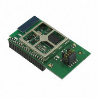
EM357-MOD-LR-ANT-TG Ember, EM357-MOD-LR-ANT-TG Datasheet - Page 103

EM357-MOD-LR-ANT-TG
Manufacturer Part Number
EM357-MOD-LR-ANT-TG
Description
MODULE EM357 PA/LNA W/ANT TG
Manufacturer
Ember
Specifications of EM357-MOD-LR-ANT-TG
Frequency
2.4GHz
Data Rate - Maximum
250kbps
Modulation Or Protocol
802.15.4 Zigbee
Voltage - Supply
2.1 V ~ 3.6 V
Current - Receiving
25mA
Current - Transmitting
42mA
Data Interface
PCB, Surface Mount
Memory Size
192kB Flash, 12kB RAM
Antenna Connector
On-Board, Chip
Operating Temperature
-40°C ~ 85°C
Package / Case
Module
Lead Free Status / RoHS Status
Lead free / RoHS Compliant
Power - Output
-
Applications
-
Sensitivity
-
Other names
636-1020
- Current page: 103 of 245
- Download datasheet (12Mb)
If the SC_UARTAUTO bit is set, nRTS is controlled automatically by hardware: nRTS is put into the low state
(asserted) when the receive FIFO has room for at least two characters, otherwise is it in the high state
(unasserted). If SC_UARTAUTO is clear, software controls the nRTS output by setting or clearing the
SC_UARTRTS bit in the SC1_UARTCFG register. Software control of nRTS is useful if the external serial device
cannot stop transmitting characters promptly when nRTS is set to the high state (deasserted).
1
8.6.5
The DMA Channels section describes how to configure and use the serial receive and transmit DMA channels.
The receive DMA channel has special provisions to record UART receive errors. When the DMA channel
transfers a character from the receive FIFO to a buffer in memory, it checks the stored parity and frame error
status flags. When an error is flagged, the SC1_RXERRA/B register is updated, marking the offset to the first
received character with a parity or frame error. Similarly if a receive overrun error occurs, the SC1_RXERRA/B
registers mark the error offset. The receive FIFO hardware generates the INT_SCRXOVF interrupt and DMA
status register indicates the error immediately, but in this case the error offset is 4 characters ahead of the
actual overflow at the input to the receive FIFO. Two conditions will clear the error indication: setting the
appropriate SC_RXDMARST bit in the SC1_DMACTRL register, or loading the appropriate DMA buffer after it has
unloaded.
8.6.6
UART interrupts are generated on the following events:
To enable CPU interrupts, set the desired interrupt bits in the second-level INT_SCxCFG register, and enable
the top-level SCx interrupt in the NVIC by writing the INT_SCx bit in the INT_CFGSET register.
FLOW
The notation xxx means that the corresponding column header below is inserted to form the field name.
Transmit FIFO empty and last character shifted out (depending on SCx_INTMODE, either the 0 to 1
transition or the high level of SC_UARTTXIDLE)
Transmit FIFO changed from full to not full (depending on SCx_INTMODE, either the 0 to 1 transition or the
high level of SC_UARTTXFREE)
Receive FIFO changed from empty to not empty (depending on SCx_INTMODE, either the 0 to 1 transition
or the high level of SC_UARTRXVAL)
Transmit DMA buffer A/B complete (1 to 0 transition of SC_TXACTA/B)
Receive DMA buffer A/B complete (1 to 0 transition of SC_RXACTA/B)
Character received with parity error
Character received with frame error
Character received and lost when receive FIFO was full (receive overrun error)
0
1
1
SC1_UARTCFG
SC_UARTxxx
DMA
Interrupts
AUTO
0
1
-
1
RTS
0/1
-
-
Table 8-12. UART RTS/CTS Flow Control Configurations
Pins Used
nCTS, nRTS
nCTS, nRTS
TXD, RXD,
TXD, RXD,
TXD, RXD
Operating Mode
No RTS/CTS flow control
Flow control using RTS/CTS with software control of nRTS:
nRTS controlled by SC_UARTRTS bit in SC1_UARTCFG register
Flow control using RTS/CTS with hardware control of nRTS:
nRTS is asserted if room for at least 2 characters in receive FIFO
Final
8-28
EM351 / EM357
120-035X-000G
Related parts for EM357-MOD-LR-ANT-TG
Image
Part Number
Description
Manufacturer
Datasheet
Request
R

Part Number:
Description:
MODULE EM357 NO PA/LNA W/ANT TG
Manufacturer:
Ember
Datasheet:

Part Number:
Description:
MODULE EM357 NO PA/LNA W/RF CONN
Manufacturer:
Ember
Datasheet:

Part Number:
Description:
MODULE EM357 PA/LNA W/RF CONN
Manufacturer:
Ember
Datasheet:

Part Number:
Description:
KIT DEV EMBER ZIGBEE W/PCWH
Manufacturer:
Custom Computer Services Inc (CCS)

Part Number:
Description:
PROGRAMMER USB FLASH EM250/260
Manufacturer:
Ember
Datasheet:

Part Number:
Description:
IC ZIGBEE SYSTEM-ON-CHIP 40-QFN
Manufacturer:
Ember
Datasheet:

Part Number:
Description:
IC ZIGBEE SYSTEM-ON-CHIP 48-QFN
Manufacturer:
Ember
Datasheet:

Part Number:
Description:
IC RF TXRX ZIGBEE 128KB 48QFN
Manufacturer:
Ember
Datasheet:

Part Number:
Description:
IC RF TXRX ZIGBEE 192KB 48QFN
Manufacturer:
Ember
Datasheet:

Part Number:
Description:
INSIGHT ADAPTER FOR EM2XX
Manufacturer:
Ember
Datasheet:

Part Number:
Description:
IAR EWARM LICENCE FOR EM35X
Manufacturer:
Ember
Datasheet:

Part Number:
Description:
KIT EVAL EM250 RF TEST
Manufacturer:
Ember
Datasheet:

Part Number:
Description:
INSIGHT ADAPTER 3 FOR EM35X
Manufacturer:
Ember
Datasheet:

Part Number:
Description:
EM250 RCM BOARD
Manufacturer:
Ember
Datasheet:

Part Number:
Description:
EM35X BREAKOUT BOARD
Manufacturer:
Ember
Datasheet:


