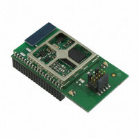
EM357-MOD-LR-ANT-TG Ember, EM357-MOD-LR-ANT-TG Datasheet - Page 59

EM357-MOD-LR-ANT-TG
Manufacturer Part Number
EM357-MOD-LR-ANT-TG
Description
MODULE EM357 PA/LNA W/ANT TG
Manufacturer
Ember
Specifications of EM357-MOD-LR-ANT-TG
Frequency
2.4GHz
Data Rate - Maximum
250kbps
Modulation Or Protocol
802.15.4 Zigbee
Voltage - Supply
2.1 V ~ 3.6 V
Current - Receiving
25mA
Current - Transmitting
42mA
Data Interface
PCB, Surface Mount
Memory Size
192kB Flash, 12kB RAM
Antenna Connector
On-Board, Chip
Operating Temperature
-40°C ~ 85°C
Package / Case
Module
Lead Free Status / RoHS Status
Lead free / RoHS Compliant
Power - Output
-
Applications
-
Sensitivity
-
Other names
636-1020
- Current page: 59 of 245
- Download datasheet (12Mb)
7.6.2
Input mode is used both for general purpose input and for on-chip peripheral inputs. Input floating mode
disables the internal pull-up and pull-down resistors, leaving the pin in a high-impedance state. Input pull-up
or pull-down mode enables either an internal pull-up or pull-down resistor based on the GPIO_PxOUT register.
Setting a bit to 0 in GPIO_PxOUT enables the pull-down and setting a bit to 1 enables the pull up.
When configured in input mode:
7.6.3
Output mode provides a general purpose output under direct software control. Regardless of whether an
output is configured as push-pull or open-drain, the GPIO’s bit in the GPIO_PxOUT register controls the
output. The GPIO_PxSET and GPIO_PxCLR registers can atomically set and clear bits within GPIO_PxOUT
register. These set and clear registers simplify software using the output port because they eliminate the need
to disable interrupts to perform an atomic read-modify-write operation of GPIO_PxOUT.
When configured in output mode:
Note: Depending on configuration and usage, GPIO_PxOUT and GPIO_PxIN may not have the same value.
7.6.4
In this mode, the output is controlled by an on-chip peripheral instead of GPIO_PxOUT and may be configured
as either push-pull or open-drain. Most peripherals require a particular output type – TWI requires an open-
drain driver, for example – but since using a peripheral does not by itself configure a pin, the GPIO_PxCFGH/L
registers must be configured properly for a peripheral’s particular needs. As described in the Configuration
section, when more than one peripheral can be the source of output data, registers in addition to
GPIO_PxCFGH/L determine which to use.
When configured in alternate output mode:
Note: Depending on configuration and usage, GPIO_PxOUT and GPIO_PxIN may not have the same value.
The output drivers are disabled.
An internal pull-up or pull-down resistor may be activated depending on GPIO_PxCFGH/L and GPIO_PxOUT.
The Schmitt trigger input is connected to the pin.
Reading GPIO_PxIN returns the input at the pin.
The input is also available to on-chip peripherals.
The output drivers are enabled and are controlled by the value written to GPIO_PxOUT:
•
•
The internal pull-up and pull-down resistors are disabled.
The Schmitt trigger input is connected to the pin.
Reading GPIO_PxIN returns the input at the pin.
Reading GPIO_PxOUT returns the last value written to the register.
The output drivers are enabled and are controlled by the output of an on-chip peripheral:
•
•
The internal pull-up and pull-down resistors are disabled.
The Schmitt trigger input is connected to the pin.
Reading GPIO_PxIN returns the input to the pin.
In open-drain mode: 0 activates the N-MOS current sink; 1 tri-states the pin.
In push-pull mode: 0 activates the N-MOS current sink; 1 activates the P-MOS current source.
In open-drain mode: 0 activates the N-MOS current sink; 1 tri-states the pin.
In push-pull mode: 0 activates the N-MOS current sink; 1 activates the P-MOS current source.
Input Mode
Output Mode
Alternate Output Mode
Final
7-6
EM351 / EM357
120-035X-000G
Related parts for EM357-MOD-LR-ANT-TG
Image
Part Number
Description
Manufacturer
Datasheet
Request
R

Part Number:
Description:
MODULE EM357 NO PA/LNA W/ANT TG
Manufacturer:
Ember
Datasheet:

Part Number:
Description:
MODULE EM357 NO PA/LNA W/RF CONN
Manufacturer:
Ember
Datasheet:

Part Number:
Description:
MODULE EM357 PA/LNA W/RF CONN
Manufacturer:
Ember
Datasheet:

Part Number:
Description:
KIT DEV EMBER ZIGBEE W/PCWH
Manufacturer:
Custom Computer Services Inc (CCS)

Part Number:
Description:
PROGRAMMER USB FLASH EM250/260
Manufacturer:
Ember
Datasheet:

Part Number:
Description:
IC ZIGBEE SYSTEM-ON-CHIP 40-QFN
Manufacturer:
Ember
Datasheet:

Part Number:
Description:
IC ZIGBEE SYSTEM-ON-CHIP 48-QFN
Manufacturer:
Ember
Datasheet:

Part Number:
Description:
IC RF TXRX ZIGBEE 128KB 48QFN
Manufacturer:
Ember
Datasheet:

Part Number:
Description:
IC RF TXRX ZIGBEE 192KB 48QFN
Manufacturer:
Ember
Datasheet:

Part Number:
Description:
INSIGHT ADAPTER FOR EM2XX
Manufacturer:
Ember
Datasheet:

Part Number:
Description:
IAR EWARM LICENCE FOR EM35X
Manufacturer:
Ember
Datasheet:

Part Number:
Description:
KIT EVAL EM250 RF TEST
Manufacturer:
Ember
Datasheet:

Part Number:
Description:
INSIGHT ADAPTER 3 FOR EM35X
Manufacturer:
Ember
Datasheet:

Part Number:
Description:
EM250 RCM BOARD
Manufacturer:
Ember
Datasheet:

Part Number:
Description:
EM35X BREAKOUT BOARD
Manufacturer:
Ember
Datasheet:


