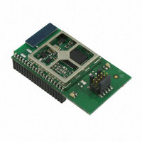
EM357-MOD-LR-ANT-TG Ember, EM357-MOD-LR-ANT-TG Datasheet - Page 155

EM357-MOD-LR-ANT-TG
Manufacturer Part Number
EM357-MOD-LR-ANT-TG
Description
MODULE EM357 PA/LNA W/ANT TG
Manufacturer
Ember
Specifications of EM357-MOD-LR-ANT-TG
Frequency
2.4GHz
Data Rate - Maximum
250kbps
Modulation Or Protocol
802.15.4 Zigbee
Voltage - Supply
2.1 V ~ 3.6 V
Current - Receiving
25mA
Current - Transmitting
42mA
Data Interface
PCB, Surface Mount
Memory Size
192kB Flash, 12kB RAM
Antenna Connector
On-Board, Chip
Operating Temperature
-40°C ~ 85°C
Package / Case
Module
Lead Free Status / RoHS Status
Lead free / RoHS Compliant
Power - Output
-
Applications
-
Sensitivity
-
Other names
636-1020
- Current page: 155 of 245
- Download datasheet (12Mb)
9.5 Registers
TIMx_CR1
TIM1_CR1
Timer 1 Control Register 1
TIM2_CR1
Timer 2 Control Register 1
Bitname
TIM_ARBE
TIM_CMS
TIM_DIR
TIM_OPM
TIM_URS
TIM_UDIS
TIM_ARBE
31
23
15
7
0
0
0
30
22
14
0
0
0
6
Bitfield
TIM_CMS
[6:5]
[7]
[4]
[3]
[2]
[1]
29
21
13
0
0
0
5
Access
RW
RW
RW
RW
RW
RW
Description
Auto-Reload Buffer Enable.
0: TIMx_ARR register is not buffered.
1: TIMx_ARR register is buffered.
Center-aligned Mode Selection.
00: Edge-aligned mode. The counter counts up or down depending on the direction bit
(TIM_DIR).
01: Center-aligned mode 1. The counter counts up and down alternatively.
Output compare interrupt flags of configured output channels (TIM_CCyS=00 in
TIMx_CCMRy register) are set only when the counter is counting down.
10: Center-aligned mode 2. The counter counts up and down alternatively.
Output compare interrupt flags of configured output channels (TIM_CCyS=00 in
TIMx_CCMRy register) are set only when the counter is counting up.
11: Center-aligned mode 3. The counter counts up and down alternatively.
Output compare interrupt flags of configured output channels (TIM_CCyS=00 in
TIMx_CCMRy register) are set both when the counter is counting up or down.
Note: Software may not switch from edge-aligned mode to center-aligned mode when the
counter is enabled (TIM_CEN=1).
Direction.
0: Counter used as up-counter.
1: Counter used as down-counter.
One Pulse Mode.
0: Counter does not stop counting at the next UEV.
1: Counter stops counting at the next UEV (and clears the bit TIM_CEN).
Update Request Source.
0: When enabled, update interrupt requests are sent as soon as registers are updated
(counter overflow/underflow, setting the TIM_UG bit, or update generation through the
slave mode controller).
1: When enabled, update interrupt requests are sent only when the counter reaches
overflow or underflow.
Update Disable.
0: A UEV is generated as soon as a counter overflow occurs, a software update is
generated, or a hardware reset is generated by the slave mode controller. Shadow
registers are then loaded with their buffer register values.
1: A UEV is not generated and shadow registers keep their value (TIMx_ARR, TIMx_PSC,
TIMx_CCRy). The counter and the prescaler are reinitialized if the TIM_UG bit is set or if a
hardware reset is received from the slave mode controller.
TIM_DIR
28
20
12
4
0
0
0
Final
9-31
TIM_OPM
27
19
11
0
0
0
3
TIM_URS
26
18
10
2
0
0
0
Address: 0x4000F000 Reset: 0x0
Address: 0x4000E000 Reset: 0x0
TIM_UDIS
25
17
0
0
9
0
1
120-035X-000G
TIM_CEN
24
16
0
0
8
0
0
Related parts for EM357-MOD-LR-ANT-TG
Image
Part Number
Description
Manufacturer
Datasheet
Request
R

Part Number:
Description:
MODULE EM357 NO PA/LNA W/ANT TG
Manufacturer:
Ember
Datasheet:

Part Number:
Description:
MODULE EM357 NO PA/LNA W/RF CONN
Manufacturer:
Ember
Datasheet:

Part Number:
Description:
MODULE EM357 PA/LNA W/RF CONN
Manufacturer:
Ember
Datasheet:

Part Number:
Description:
KIT DEV EMBER ZIGBEE W/PCWH
Manufacturer:
Custom Computer Services Inc (CCS)

Part Number:
Description:
PROGRAMMER USB FLASH EM250/260
Manufacturer:
Ember
Datasheet:

Part Number:
Description:
IC ZIGBEE SYSTEM-ON-CHIP 40-QFN
Manufacturer:
Ember
Datasheet:

Part Number:
Description:
IC ZIGBEE SYSTEM-ON-CHIP 48-QFN
Manufacturer:
Ember
Datasheet:

Part Number:
Description:
IC RF TXRX ZIGBEE 128KB 48QFN
Manufacturer:
Ember
Datasheet:

Part Number:
Description:
IC RF TXRX ZIGBEE 192KB 48QFN
Manufacturer:
Ember
Datasheet:

Part Number:
Description:
INSIGHT ADAPTER FOR EM2XX
Manufacturer:
Ember
Datasheet:

Part Number:
Description:
IAR EWARM LICENCE FOR EM35X
Manufacturer:
Ember
Datasheet:

Part Number:
Description:
KIT EVAL EM250 RF TEST
Manufacturer:
Ember
Datasheet:

Part Number:
Description:
INSIGHT ADAPTER 3 FOR EM35X
Manufacturer:
Ember
Datasheet:

Part Number:
Description:
EM250 RCM BOARD
Manufacturer:
Ember
Datasheet:

Part Number:
Description:
EM35X BREAKOUT BOARD
Manufacturer:
Ember
Datasheet:


