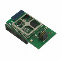
EM357-MOD-LR-ANT-TG Ember, EM357-MOD-LR-ANT-TG Datasheet - Page 207

EM357-MOD-LR-ANT-TG
Manufacturer Part Number
EM357-MOD-LR-ANT-TG
Description
MODULE EM357 PA/LNA W/ANT TG
Manufacturer
Ember
Specifications of EM357-MOD-LR-ANT-TG
Frequency
2.4GHz
Data Rate - Maximum
250kbps
Modulation Or Protocol
802.15.4 Zigbee
Voltage - Supply
2.1 V ~ 3.6 V
Current - Receiving
25mA
Current - Transmitting
42mA
Data Interface
PCB, Surface Mount
Memory Size
192kB Flash, 12kB RAM
Antenna Connector
On-Board, Chip
Operating Temperature
-40°C ~ 85°C
Package / Case
Module
Lead Free Status / RoHS Status
Lead free / RoHS Compliant
Power - Output
-
Applications
-
Sensitivity
-
Other names
636-1020
- Current page: 207 of 245
- Download datasheet (12Mb)
Given a peripheral, ‘periph’, the Event Manager registers (INT_periphCFG and INT_periphFLAG) follow the
form:
If a bit in the INT_periphCFG register is set after the corresponding bit in the INT_periphFLAG register is set
then the second-level interrupt propagates into the top-level interrupts. The interrupt flags (signals) from the
second-level interrupts into the top-level interrupts are level-sensitive. If a top-level NVIC interrupt is driven
by a second-level EM interrupt, then the top-level NVIC interrupt cannot be cleared until all second-level EM
interrupts are cleared.
The INT_periphFLAG register bits are designed to remain set if the second-level interrupt event re-occurs at
the same moment as the INT_periphFLAG register bit is being cleared. This ensures the re-occurring second-
level interrupt event is not missed.
If another enabled second-level interrupt event of the same type occurs before the first interrupt event is
cleared, the second interrupt event is lost because no counting or queuing is used. However, this condition is
detected and stored in the top-level INT_MISS register to facilitate software detection of such problems. The
INT_MISS register is “acknowledged” in the same way as the INT_periphFLAG register—by writing a 1 into the
corresponding bit to be cleared.
Table 11-2 provides a map of all peripheral interrupts. This map lists the top-level NVIC Interrupt bits and, if
there is one, the corresponding second-level EM Interrupt register bits that feed the top-level interrupts.
INT_periphCFG enables and disables second-level interrupts. Writing 1 to a bit in the INT_periphCFG
register enables the second-level interrupt. Writing 0 to a bit in the INT_periphCFG register disables it.
The INT_periphCFG register behaves like a mask, and is responsible for allowing the INT_periphFLAG bits
to propagate into the top-level NVIC interrupts.
INT_periphFLAG indicates second-level interrupts that have occurred. Writing 1 to a bit in a
INT_periphFLAG register clears the second-level interrupt. Writing 0 to any bit in the INT_periphFLAG
register is ineffective. The INT_periphFLAG register is always active and may be set or cleared at any time,
meaning if any second-level interrupt occurs, then the corresponding bit in the INT_periphFLAG register is
set regardless of the state of INT_periphCFG.
source interrupt events
OR
AND
peripheral interrupt instance
S
latch
OR
Q
AND
R
Figure 11-1. Peripheral Interrupts Block Diagram
INT_periphFLAG
write 1
read
INT_periphCFG
Final
11-4
interrupts from all peripherals
interrupts into NVIC/CPU
OR
S
S
latch
latch
Q
Q
AND
R
R
S
latch
Q
R
EM351 / EM357
write 1
write 1
write 1
write 1
write 1
INT_PENDCLR
INT_PENDSET
INT_CFGCLR
INT_CFGSET
read
read
INT_MISS
read
120-035X-000G
Related parts for EM357-MOD-LR-ANT-TG
Image
Part Number
Description
Manufacturer
Datasheet
Request
R

Part Number:
Description:
MODULE EM357 NO PA/LNA W/ANT TG
Manufacturer:
Ember
Datasheet:

Part Number:
Description:
MODULE EM357 NO PA/LNA W/RF CONN
Manufacturer:
Ember
Datasheet:

Part Number:
Description:
MODULE EM357 PA/LNA W/RF CONN
Manufacturer:
Ember
Datasheet:

Part Number:
Description:
KIT DEV EMBER ZIGBEE W/PCWH
Manufacturer:
Custom Computer Services Inc (CCS)

Part Number:
Description:
PROGRAMMER USB FLASH EM250/260
Manufacturer:
Ember
Datasheet:

Part Number:
Description:
IC ZIGBEE SYSTEM-ON-CHIP 40-QFN
Manufacturer:
Ember
Datasheet:

Part Number:
Description:
IC ZIGBEE SYSTEM-ON-CHIP 48-QFN
Manufacturer:
Ember
Datasheet:

Part Number:
Description:
IC RF TXRX ZIGBEE 128KB 48QFN
Manufacturer:
Ember
Datasheet:

Part Number:
Description:
IC RF TXRX ZIGBEE 192KB 48QFN
Manufacturer:
Ember
Datasheet:

Part Number:
Description:
INSIGHT ADAPTER FOR EM2XX
Manufacturer:
Ember
Datasheet:

Part Number:
Description:
IAR EWARM LICENCE FOR EM35X
Manufacturer:
Ember
Datasheet:

Part Number:
Description:
KIT EVAL EM250 RF TEST
Manufacturer:
Ember
Datasheet:

Part Number:
Description:
INSIGHT ADAPTER 3 FOR EM35X
Manufacturer:
Ember
Datasheet:

Part Number:
Description:
EM250 RCM BOARD
Manufacturer:
Ember
Datasheet:

Part Number:
Description:
EM35X BREAKOUT BOARD
Manufacturer:
Ember
Datasheet:


