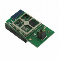
EM357-MOD-LR-ANT-TG Ember, EM357-MOD-LR-ANT-TG Datasheet - Page 223

EM357-MOD-LR-ANT-TG
Manufacturer Part Number
EM357-MOD-LR-ANT-TG
Description
MODULE EM357 PA/LNA W/ANT TG
Manufacturer
Ember
Specifications of EM357-MOD-LR-ANT-TG
Frequency
2.4GHz
Data Rate - Maximum
250kbps
Modulation Or Protocol
802.15.4 Zigbee
Voltage - Supply
2.1 V ~ 3.6 V
Current - Receiving
25mA
Current - Transmitting
42mA
Data Interface
PCB, Surface Mount
Memory Size
192kB Flash, 12kB RAM
Antenna Connector
On-Board, Chip
Operating Temperature
-40°C ~ 85°C
Package / Case
Module
Lead Free Status / RoHS Status
Lead free / RoHS Compliant
Power - Output
-
Applications
-
Sensitivity
-
Other names
636-1020
- Current page: 223 of 245
- Download datasheet (12Mb)
17 Serial Wire and JTAG (SWJ) Interface
The EM35x includes a standard Serial Wire and JTAG (SWJ) Interface. The SWJ is the primary debug and
programming interface of the EM35x. The SWJ gives debug tools access to the internal buses of the EM35x,
and allows for non-intrusive memory and register access as well as CPU halt-step style debugging. Therefore,
any design implementing the EM35x should make the SWJ signals readily available.
Serial Wire is an ARM® standard, bi-directional, two-wire protocol designed to replace JTAG, and provides all
the normal JTAG debug and test functionality. JTAG is a standard five-wire protocol providing debug and test
functionality. In addition, the two Serial Wire signals (SWDIO and SWCLK) are overlaid on two of the JTAG
signals (JTMS and JTCK). This keeps the design compact and allows debug tools to switch between Serial Wire
and JTAG as needed, without changing pin connections.
While Serial Wire and JTAG offer the same debug and test functionality, Ember recommends Serial Wire.
Serial Wire uses only two pins instead of five, and offers a simple communication protocol, high performance
data rates, low power, built-in error detection, and protection from glitches.
The ARM® CoreSight
illustrated in Figure 17-1, the DAP includes two primary components: a debug port (the SWJ-DP) and an access
port (the AHB-AP). The SWJ-DP provides external debug access, while the AHB-AP provides internal bus
access. An external debug tool connected to the EM35x’s debug pins communicates with the SWJ-DP. The
SWJ-DP then communicates with the AHB-AP. Finally, the AHB-AP communicates on the internal bus.
Serial Wire and JTAG share five pins:
Note: The SWJ pins are forced functions, and their corresponding GPIO_PxCFGH/L configurations are
overridden when the EM35x resets. An application must disable all debug SWJ debug functionality to reclaim
any of the four SWJ GPIOs: PC0, PC2, PC3, and PC4.
Since these pins can be repurposed, refer to Chapter 1, Pin Assignments, and Section 7.3, Forced Functions, in
Chapter 7, GPIO, for complete pin descriptions and configurations.
For further information on the SWJ, contact Ember support for Application Notes and ARM
documentation.
JRST
JTDO
JTDI
SWDIO/JTMS
SWCLK/JTCK
pins
TM
Debug Access Port (DAP) comprises the Serial Wire and JTAG Interface (SWJ). As
SWJ-DP
select
Figure 17-1. SWJ Block Diagram
Final
17-1
interface
interface
JTAG
SWJ-DP
SW
SWJ-DAP
AP interface
Control and
AHB-AP
EM351 / EM357
AHB
®
CoreSight
120-035X-000G
TM
Related parts for EM357-MOD-LR-ANT-TG
Image
Part Number
Description
Manufacturer
Datasheet
Request
R

Part Number:
Description:
MODULE EM357 NO PA/LNA W/ANT TG
Manufacturer:
Ember
Datasheet:

Part Number:
Description:
MODULE EM357 NO PA/LNA W/RF CONN
Manufacturer:
Ember
Datasheet:

Part Number:
Description:
MODULE EM357 PA/LNA W/RF CONN
Manufacturer:
Ember
Datasheet:

Part Number:
Description:
KIT DEV EMBER ZIGBEE W/PCWH
Manufacturer:
Custom Computer Services Inc (CCS)

Part Number:
Description:
PROGRAMMER USB FLASH EM250/260
Manufacturer:
Ember
Datasheet:

Part Number:
Description:
IC ZIGBEE SYSTEM-ON-CHIP 40-QFN
Manufacturer:
Ember
Datasheet:

Part Number:
Description:
IC ZIGBEE SYSTEM-ON-CHIP 48-QFN
Manufacturer:
Ember
Datasheet:

Part Number:
Description:
IC RF TXRX ZIGBEE 128KB 48QFN
Manufacturer:
Ember
Datasheet:

Part Number:
Description:
IC RF TXRX ZIGBEE 192KB 48QFN
Manufacturer:
Ember
Datasheet:

Part Number:
Description:
INSIGHT ADAPTER FOR EM2XX
Manufacturer:
Ember
Datasheet:

Part Number:
Description:
IAR EWARM LICENCE FOR EM35X
Manufacturer:
Ember
Datasheet:

Part Number:
Description:
KIT EVAL EM250 RF TEST
Manufacturer:
Ember
Datasheet:

Part Number:
Description:
INSIGHT ADAPTER 3 FOR EM35X
Manufacturer:
Ember
Datasheet:

Part Number:
Description:
EM250 RCM BOARD
Manufacturer:
Ember
Datasheet:

Part Number:
Description:
EM35X BREAKOUT BOARD
Manufacturer:
Ember
Datasheet:


