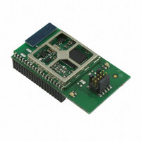
EM357-MOD-LR-ANT-TG Ember, EM357-MOD-LR-ANT-TG Datasheet - Page 34

EM357-MOD-LR-ANT-TG
Manufacturer Part Number
EM357-MOD-LR-ANT-TG
Description
MODULE EM357 PA/LNA W/ANT TG
Manufacturer
Ember
Specifications of EM357-MOD-LR-ANT-TG
Frequency
2.4GHz
Data Rate - Maximum
250kbps
Modulation Or Protocol
802.15.4 Zigbee
Voltage - Supply
2.1 V ~ 3.6 V
Current - Receiving
25mA
Current - Transmitting
42mA
Data Interface
PCB, Surface Mount
Memory Size
192kB Flash, 12kB RAM
Antenna Connector
On-Board, Chip
Operating Temperature
-40°C ~ 85°C
Package / Case
Module
Lead Free Status / RoHS Status
Lead free / RoHS Compliant
Power - Output
-
Applications
-
Sensitivity
-
Other names
636-1020
- Current page: 34 of 245
- Download datasheet (12Mb)
5.2.1
5.2.1.1 Flash Overview
The EM351 provides a total of 132 kB of flash memory and the EM357 provides a total of 196 kB of flash
memory. The flash memory is provided in three separate blocks:
The MFB is divided into 2048-byte pages. The EM351 has 64 pages and the EM357 has 96 pages. The CIB is a
single 2048-byte page. The FIB is a single 2048-byte page. The smallest erasable unit is one page and the
smallest writable unit is an aligned 16-bit half-word. The flash is rated to have a guaranteed 20,000
write/erase cycles. The flash cell has been qualified for a data retention time of >100 years at room
temperature.
Flash may be programmed either through the Serial Wire/JTAG interface or through bootloader software.
Programming flash through Serial Wire/JTAG requires the assistance of RAM-based utility code. Programming
through a bootloader requires Ember software for over-the-air loading or serial link loading. A simplified,
serial-link-only bootloader is also available preprogrammed into the FIB.
5.2.1.2 Main Flash Block
The start of the MFB is mapped to both address 0x00000000 and address 0x08000000 in normal boot mode, but
is mapped only to address 0x08000000 in serial-link-only bootload mode (see also section 7.5, Boot
Configuration in Chapter 7, GPIO). Consequently, it is recommended that software intended to execute from
the MFB is designed to operate from the upper address, 0x08000000, since this address mapping is always
available in all modes.
The MFB stores all program instructions and constant data. A small portion of the MFB is devoted to non-
volatile token storage using Ember’s Simulated EEPROM system.
5.2.1.3 Fixed Information Block
The 2 kB FIB is used to store fixed manufacturing data including serial numbers and calibration values. The
start of the FIB is mapped to address 0x08040000. This block can only be programmed during production by
Ember.
The FIB also contains a small, serial-link-only bootloader. In serial bootload mode, the start of the FIB is
mapped to both address 0x00000000 and address 0x08040000 so the bootloader may be executed out of reset.
5.2.1.4 Customer Information Block
The 2048 byte CIB can be used to store customer data. The start of the CIB is mapped to address 0x08040800.
The CIB cannot be executed.
The first eight half-words of the CIB are dedicated to special storage called option bytes. An option byte is a
16 bit quantity of flash where the lower 8 bits contain the data and the upper 8 contain the inverse of the
lower 8 bits. The upper 8 bits are automatically generated by hardware and cannot be written to by the user,
see Table 5-1.
The option byte hardware also verifies the inverse of each option byte when exiting from reset and generates
an error, which prevents the CPU from executing code, if a discrepancy is found. All of this is transparent to
the user.
Main Flash Block (MFB)
Fixed Information Block (FIB)
Customer Information Block (CIB)
Flash Memory
Final
5-4
EM351 / EM357
120-035X-000G
Related parts for EM357-MOD-LR-ANT-TG
Image
Part Number
Description
Manufacturer
Datasheet
Request
R

Part Number:
Description:
MODULE EM357 NO PA/LNA W/ANT TG
Manufacturer:
Ember
Datasheet:

Part Number:
Description:
MODULE EM357 NO PA/LNA W/RF CONN
Manufacturer:
Ember
Datasheet:

Part Number:
Description:
MODULE EM357 PA/LNA W/RF CONN
Manufacturer:
Ember
Datasheet:

Part Number:
Description:
KIT DEV EMBER ZIGBEE W/PCWH
Manufacturer:
Custom Computer Services Inc (CCS)

Part Number:
Description:
PROGRAMMER USB FLASH EM250/260
Manufacturer:
Ember
Datasheet:

Part Number:
Description:
IC ZIGBEE SYSTEM-ON-CHIP 40-QFN
Manufacturer:
Ember
Datasheet:

Part Number:
Description:
IC ZIGBEE SYSTEM-ON-CHIP 48-QFN
Manufacturer:
Ember
Datasheet:

Part Number:
Description:
IC RF TXRX ZIGBEE 128KB 48QFN
Manufacturer:
Ember
Datasheet:

Part Number:
Description:
IC RF TXRX ZIGBEE 192KB 48QFN
Manufacturer:
Ember
Datasheet:

Part Number:
Description:
INSIGHT ADAPTER FOR EM2XX
Manufacturer:
Ember
Datasheet:

Part Number:
Description:
IAR EWARM LICENCE FOR EM35X
Manufacturer:
Ember
Datasheet:

Part Number:
Description:
KIT EVAL EM250 RF TEST
Manufacturer:
Ember
Datasheet:

Part Number:
Description:
INSIGHT ADAPTER 3 FOR EM35X
Manufacturer:
Ember
Datasheet:

Part Number:
Description:
EM250 RCM BOARD
Manufacturer:
Ember
Datasheet:

Part Number:
Description:
EM35X BREAKOUT BOARD
Manufacturer:
Ember
Datasheet:


