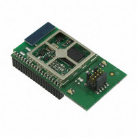
EM357-MOD-LR-ANT-TG Ember, EM357-MOD-LR-ANT-TG Datasheet - Page 4

EM357-MOD-LR-ANT-TG
Manufacturer Part Number
EM357-MOD-LR-ANT-TG
Description
MODULE EM357 PA/LNA W/ANT TG
Manufacturer
Ember
Specifications of EM357-MOD-LR-ANT-TG
Frequency
2.4GHz
Data Rate - Maximum
250kbps
Modulation Or Protocol
802.15.4 Zigbee
Voltage - Supply
2.1 V ~ 3.6 V
Current - Receiving
25mA
Current - Transmitting
42mA
Data Interface
PCB, Surface Mount
Memory Size
192kB Flash, 12kB RAM
Antenna Connector
On-Board, Chip
Operating Temperature
-40°C ~ 85°C
Package / Case
Module
Lead Free Status / RoHS Status
Lead free / RoHS Compliant
Power - Output
-
Applications
-
Sensitivity
-
Other names
636-1020
- Current page: 4 of 245
- Download datasheet (12Mb)
9
8.4 SPI - Slave Mode
8.5 TWI - Two Wire serial Interfaces
8.6 UART - Universal Asynchronous
8.7 DMA Channels
General Purpose Timers (TIM1 and
TIM2)
9.1 Introduction
9.2 GPIO Usage
9.3 Timer Functional Description
8.3.2
8.3.3
8.3.4
8.3.5
8.4.1
8.4.2
8.4.3
8.4.4
8.4.5
8.4.6
8.5.1
8.5.2
8.5.3
8.5.4
8.5.5
Receiver / Transmitter
8.6.1
8.6.2
8.6.3
8.6.4
8.6.5
8.6.6
8.6.7
8.7.1
9.3.1
9.3.2
9.3.3
9.3.4
9.3.5
9.3.6
9.3.7
9.3.8
9.3.9
9.3.10 One-Pulse Mode
9.3.11 Encoder Interface Mode
9.3.12 Timer Input XOR Function 9-22
9.3.13 Timers and External Trigger
9.3.14 Timer Synchronization
9.3.15 Timer Signal
Set Up and Configuration
Operation
Interrupts
Registers
GPIO Usage
Set Up and Configuration 8-15
Operation
DMA
Interrupts
Registers
GPIO Usage
Set Up and Configuration 8-18
Constructing Frames
Interrupts
Registers
GPIO Usage
Set Up and Configuration 8-25
FIFOs
RTS/CTS Flow control
DMA
Interrupts
Registers
Registers
Time-Base Unit
Counter Modes
Clock Selection
Capture/Compare
Input Capture Mode
PWM Input Mode
Forced Output Mode
Output Compare Mode
PWM Mode
Channels
Synchronization
Descriptions
Final
8-10
8-14
8-14
8-16
8-17
8-17
8-18
8-18
8-18
8-19
8-21
8-22
8-24
8-24
8-27
8-27
8-28
8-28
8-29
8-32
8-34
9-12
9-13
9-14
9-15
9-15
9-16
9-19
9-20
9-22
9-25
9-29
9-1
8-7
8-8
8-9
9-1
9-3
9-3
9-3
9-4
9-9
EM351 / EM357 Datasheet
10 ADC (Analog to Digital
11 Interrupt System
12 Trace Port Interface Unit (TPIU) 12-1
13 Instrumentation Trace Macrocell
14 Data Watchpoint and Trace
15 Flash Patch and Breakpoint
16 Integrated Voltage Regulator
17 Serial Wire and JTAG (SWJ)
18 Typical Application
19 Mechanical Details
20 Part Marking
21 Ordering Information
22 Shipping Box Label
23 Revision History
Appendix A Register Address Table
9.4 Interrupts
9.5 Registers
Converter)
10.1 Setup and Configuration
10.2 Interrupts
10.3 Operation
10.4 Calibration
10.5 ADC Key Parameters
10.6 Registers
11.1 Nested Vectored Interrupt
11.2 Event Manager
11.3 Non-maskable Interrupt (NMI)
11.4 Faults
11.5 Registers
(ITM)
(DWT)
(FPB)
Interface
19.1 QFN48 Footprint
19.2 Solder Temperature Profile
10.1.1 GPIO Usage
10.1.2 Voltage Reference
10.1.3 Offset/Gain Correction
10.1.4 DMA
10.1.5 ADC Configuration
Controller (NVIC)
Recommendations
Register
120-035X-000G
10-13
10-1
11-1
13-1
14-1
15-1
16-1
17-1
18-1
19-1
20-1
21-1
22-1
23-1
9-30
9-31
10-1
10-2
10-2
10-2
10-3
10-3
10-5
10-6
10-7
10-8
11-1
11-3
11-6
11-6
11-7
19-1
19-3
A-1
Related parts for EM357-MOD-LR-ANT-TG
Image
Part Number
Description
Manufacturer
Datasheet
Request
R

Part Number:
Description:
MODULE EM357 NO PA/LNA W/ANT TG
Manufacturer:
Ember
Datasheet:

Part Number:
Description:
MODULE EM357 NO PA/LNA W/RF CONN
Manufacturer:
Ember
Datasheet:

Part Number:
Description:
MODULE EM357 PA/LNA W/RF CONN
Manufacturer:
Ember
Datasheet:

Part Number:
Description:
KIT DEV EMBER ZIGBEE W/PCWH
Manufacturer:
Custom Computer Services Inc (CCS)

Part Number:
Description:
PROGRAMMER USB FLASH EM250/260
Manufacturer:
Ember
Datasheet:

Part Number:
Description:
IC ZIGBEE SYSTEM-ON-CHIP 40-QFN
Manufacturer:
Ember
Datasheet:

Part Number:
Description:
IC ZIGBEE SYSTEM-ON-CHIP 48-QFN
Manufacturer:
Ember
Datasheet:

Part Number:
Description:
IC RF TXRX ZIGBEE 128KB 48QFN
Manufacturer:
Ember
Datasheet:

Part Number:
Description:
IC RF TXRX ZIGBEE 192KB 48QFN
Manufacturer:
Ember
Datasheet:

Part Number:
Description:
INSIGHT ADAPTER FOR EM2XX
Manufacturer:
Ember
Datasheet:

Part Number:
Description:
IAR EWARM LICENCE FOR EM35X
Manufacturer:
Ember
Datasheet:

Part Number:
Description:
KIT EVAL EM250 RF TEST
Manufacturer:
Ember
Datasheet:

Part Number:
Description:
INSIGHT ADAPTER 3 FOR EM35X
Manufacturer:
Ember
Datasheet:

Part Number:
Description:
EM250 RCM BOARD
Manufacturer:
Ember
Datasheet:

Part Number:
Description:
EM35X BREAKOUT BOARD
Manufacturer:
Ember
Datasheet:


