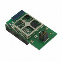
EM357-MOD-LR-ANT-TG Ember, EM357-MOD-LR-ANT-TG Datasheet - Page 61

EM357-MOD-LR-ANT-TG
Manufacturer Part Number
EM357-MOD-LR-ANT-TG
Description
MODULE EM357 PA/LNA W/ANT TG
Manufacturer
Ember
Specifications of EM357-MOD-LR-ANT-TG
Frequency
2.4GHz
Data Rate - Maximum
250kbps
Modulation Or Protocol
802.15.4 Zigbee
Voltage - Supply
2.1 V ~ 3.6 V
Current - Receiving
25mA
Current - Transmitting
42mA
Data Interface
PCB, Surface Mount
Memory Size
192kB Flash, 12kB RAM
Antenna Connector
On-Board, Chip
Operating Temperature
-40°C ~ 85°C
Package / Case
Module
Lead Free Status / RoHS Status
Lead free / RoHS Compliant
Power - Output
-
Applications
-
Sensitivity
-
Other names
636-1020
- Current page: 61 of 245
- Download datasheet (12Mb)
7.9
7.10
Debug Control and Status
GPIO Signal Assignment Summary
In some cases, it may be useful to assign IRQC or IRQD to an input also in use by a peripheral, for example to
generate an interrupt from the slave select signal (nSSEL) in an SPI slave mode interface.
Refer to Chapter 11, Interrupt System, for further information regarding the EM35x interrupt system.
Two GPIO registers are largely concerned with debugger functions. GPIO_DBGCFG can disable debugger
operation, but has other miscellaneous control bits as well. GPIO_DBGSTAT, a read-only register, returns
status related to debugger activity (GPIO_FORCEDBG and GPIO_SWEN), as well a flag (GPIO_BOOTMODE)
indicating whether nBOOTMODE was asserted at the last power-on or nRESET-based reset.
The GPIO signal assignments are shown in Table 7-5.
GPIO_IRQxSEL
0
1
2
3
4
5
6
7
GPIO
PA0
PA1
PA2
PA3
PA4
PA5
PA6
PA7
Table 7-4. IRQC/D GPIO Selection
Final
GPIO_IRQxSEL
7-8
10
11
12
13
14
15
8
9
GPIO
PB0
PB1
PB2
PB3
PB4
PB5
PB6
PB7
EM351 / EM357
GPIO_IRQxSEL
16
17
18
19
20
21
22
23
120-035X-000G
GPIO
PC0
PC1
PC2
PC3
PC4
PC5
PC6
PC7
Related parts for EM357-MOD-LR-ANT-TG
Image
Part Number
Description
Manufacturer
Datasheet
Request
R

Part Number:
Description:
MODULE EM357 NO PA/LNA W/ANT TG
Manufacturer:
Ember
Datasheet:

Part Number:
Description:
MODULE EM357 NO PA/LNA W/RF CONN
Manufacturer:
Ember
Datasheet:

Part Number:
Description:
MODULE EM357 PA/LNA W/RF CONN
Manufacturer:
Ember
Datasheet:

Part Number:
Description:
KIT DEV EMBER ZIGBEE W/PCWH
Manufacturer:
Custom Computer Services Inc (CCS)

Part Number:
Description:
PROGRAMMER USB FLASH EM250/260
Manufacturer:
Ember
Datasheet:

Part Number:
Description:
IC ZIGBEE SYSTEM-ON-CHIP 40-QFN
Manufacturer:
Ember
Datasheet:

Part Number:
Description:
IC ZIGBEE SYSTEM-ON-CHIP 48-QFN
Manufacturer:
Ember
Datasheet:

Part Number:
Description:
IC RF TXRX ZIGBEE 128KB 48QFN
Manufacturer:
Ember
Datasheet:

Part Number:
Description:
IC RF TXRX ZIGBEE 192KB 48QFN
Manufacturer:
Ember
Datasheet:

Part Number:
Description:
INSIGHT ADAPTER FOR EM2XX
Manufacturer:
Ember
Datasheet:

Part Number:
Description:
IAR EWARM LICENCE FOR EM35X
Manufacturer:
Ember
Datasheet:

Part Number:
Description:
KIT EVAL EM250 RF TEST
Manufacturer:
Ember
Datasheet:

Part Number:
Description:
INSIGHT ADAPTER 3 FOR EM35X
Manufacturer:
Ember
Datasheet:

Part Number:
Description:
EM250 RCM BOARD
Manufacturer:
Ember
Datasheet:

Part Number:
Description:
EM35X BREAKOUT BOARD
Manufacturer:
Ember
Datasheet:


