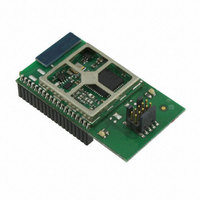
EM357-MOD-LR-ANT-TG Ember, EM357-MOD-LR-ANT-TG Datasheet - Page 221

EM357-MOD-LR-ANT-TG
Manufacturer Part Number
EM357-MOD-LR-ANT-TG
Description
MODULE EM357 PA/LNA W/ANT TG
Manufacturer
Ember
Specifications of EM357-MOD-LR-ANT-TG
Frequency
2.4GHz
Data Rate - Maximum
250kbps
Modulation Or Protocol
802.15.4 Zigbee
Voltage - Supply
2.1 V ~ 3.6 V
Current - Receiving
25mA
Current - Transmitting
42mA
Data Interface
PCB, Surface Mount
Memory Size
192kB Flash, 12kB RAM
Antenna Connector
On-Board, Chip
Operating Temperature
-40°C ~ 85°C
Package / Case
Module
Lead Free Status / RoHS Status
Lead free / RoHS Compliant
Power - Output
-
Applications
-
Sensitivity
-
Other names
636-1020
- Current page: 221 of 245
- Download datasheet (12Mb)
16 Integrated Voltage Regulator
The EM35x integrates two low dropout regulators to provide 1.8 V and 1.25 V power supplies, as detailed in
Table 16-1. The 1V8 regulator supplies the analog and memories, and the 1V25 regulator supplies the digital
core. In deep sleep the voltage regulators are disabled.
When enabled, the 1V8 regulator steps down the pads supply voltage (VDD_PADS) from a nominal 3.0 V to
1.8 V. The regulator output pin (VREG_OUT) must be decoupled externally with a suitable capacitor.
VREG_OUT should be connected to the 1.8 V supply pins VDDA, VDD_RF, VDD_VCO, VDD_SYNTH, VDD_IF, and
VDD_MEM. The 1V8 regulator can supply a maximum of 50 mA.
When enabled, the 1V25 regulator steps down VDD_PADS to 1.25 V. The regulator output pin (VDD_CORE,
Pin 17) must be decoupled externally with a suitable capacitor. It should connect to the other VDD_CORE pin
(Pin 44). The 1V25 regulator can supply a maximum of 10 mA.
The regulators are controlled by the digital portion of the chip as described in Chapter 6, System Modules.
An example of decoupling capacitors and PCB layout can be found in the application notes (see Ember’s
various EM35x reference design documentation).
Spec Point
Supply range for regulator
1V8 regulator output
1V8 regulator output after
reset
1V25 regulator output
1V25 regulator output
after reset
1V8 regulator capacitor
1V25 regulator capacitor
1V8 regulator output
current
1V25 regulator output
current
No load current
1V8 regulator current
limit
1V25 regulator current
limit
1V8 regulator start-up
time
1V25 regulator start-up
time
Table 16-1. Integrated Voltage Regulator Specifications
Min.
-5%
-5%
-5%
-5%
2.1
0
0
Typ.
1.75
1.25
1.45
600
200
1.8
2.2
1.0
25
50
50
Final
16-1
Max.
+5%
+5%
+5%
+5%
3.6
50
10
Units
mA
mA
mA
mA
µF
µA
µF
µs
µs
V
V
V
Comments
VDD_PADS
Regulator output after initialization
Regulator output after reset
Regulator output after initialization
Regulator output after reset
Low ESR tantalum capacitor
ESR greater than 2 Ω
ESR less than 10 Ω
de-coupling less than 100 nF ceramic
Ceramic capacitor (0603)
Regulator output current
Regulator output current
No load current (bandgap and regulators)
Short circuit current limit
Short circuit current limit
0 V to POR threshold
2.2 µF capacitor
0 V to POR threshold
1.0 µF capacitor
EM351 / EM357
120-035X-000G
Related parts for EM357-MOD-LR-ANT-TG
Image
Part Number
Description
Manufacturer
Datasheet
Request
R

Part Number:
Description:
MODULE EM357 NO PA/LNA W/ANT TG
Manufacturer:
Ember
Datasheet:

Part Number:
Description:
MODULE EM357 NO PA/LNA W/RF CONN
Manufacturer:
Ember
Datasheet:

Part Number:
Description:
MODULE EM357 PA/LNA W/RF CONN
Manufacturer:
Ember
Datasheet:

Part Number:
Description:
KIT DEV EMBER ZIGBEE W/PCWH
Manufacturer:
Custom Computer Services Inc (CCS)

Part Number:
Description:
PROGRAMMER USB FLASH EM250/260
Manufacturer:
Ember
Datasheet:

Part Number:
Description:
IC ZIGBEE SYSTEM-ON-CHIP 40-QFN
Manufacturer:
Ember
Datasheet:

Part Number:
Description:
IC ZIGBEE SYSTEM-ON-CHIP 48-QFN
Manufacturer:
Ember
Datasheet:

Part Number:
Description:
IC RF TXRX ZIGBEE 128KB 48QFN
Manufacturer:
Ember
Datasheet:

Part Number:
Description:
IC RF TXRX ZIGBEE 192KB 48QFN
Manufacturer:
Ember
Datasheet:

Part Number:
Description:
INSIGHT ADAPTER FOR EM2XX
Manufacturer:
Ember
Datasheet:

Part Number:
Description:
IAR EWARM LICENCE FOR EM35X
Manufacturer:
Ember
Datasheet:

Part Number:
Description:
KIT EVAL EM250 RF TEST
Manufacturer:
Ember
Datasheet:

Part Number:
Description:
INSIGHT ADAPTER 3 FOR EM35X
Manufacturer:
Ember
Datasheet:

Part Number:
Description:
EM250 RCM BOARD
Manufacturer:
Ember
Datasheet:

Part Number:
Description:
EM35X BREAKOUT BOARD
Manufacturer:
Ember
Datasheet:


