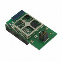
EM357-MOD-LR-ANT-TG Ember, EM357-MOD-LR-ANT-TG Datasheet - Page 154

EM357-MOD-LR-ANT-TG
Manufacturer Part Number
EM357-MOD-LR-ANT-TG
Description
MODULE EM357 PA/LNA W/ANT TG
Manufacturer
Ember
Specifications of EM357-MOD-LR-ANT-TG
Frequency
2.4GHz
Data Rate - Maximum
250kbps
Modulation Or Protocol
802.15.4 Zigbee
Voltage - Supply
2.1 V ~ 3.6 V
Current - Receiving
25mA
Current - Transmitting
42mA
Data Interface
PCB, Surface Mount
Memory Size
192kB Flash, 12kB RAM
Antenna Connector
On-Board, Chip
Operating Temperature
-40°C ~ 85°C
Package / Case
Module
Lead Free Status / RoHS Status
Lead free / RoHS Compliant
Power - Output
-
Applications
-
Sensitivity
-
Other names
636-1020
- Current page: 154 of 245
- Download datasheet (12Mb)
9.4 Interrupts
Each timer has its own top-level NVIC interrupt. Writing 1 to the INT_TIMx bit in the INT_CFGSET register
enables the TIMx interrupt, and writing 1 to the INT_TIMx bit in the INT_CFGCLR register disables it. Chapter
11, Interrupt System describes the interrupt system in detail.
Several kinds of timer events can generate a timer interrupt, and each has a status flag in the INT_TIMxFLAG
register to identify the reason(s) for the interrupt:
Clear bits in INT_TIMxFLAG by writing a 1 to their bit position. When a channel is in capture mode, reading the
TIMx_CCRy register will also clear the INT_TIMCCRyIF bit.
The INT_TIMxCFG register controls whether or not the INT_TIMxFLAG bits actually request a top-level NVIC
timer interrupt. Only the events whose bits are set to 1 in INT_TIMxCFG can do so.
If an input capture or output compare event occurs and its INT_TIMMISSCCyIF is already set, the corresponding
capture/compare missed flag is set in the INT_TMRxMISS register. Clear a bit in the INT_TMRxMISS register by
writing a 1 to it.
INT_TIMTIF – set by a rising edge on an external trigger, either edge in gated mode
INT_TIMCCRyIF – set by a channel y input capture or output compare event
INT_TIMUIF – set by a UEV
Final
9-30
120-035X-000G
Related parts for EM357-MOD-LR-ANT-TG
Image
Part Number
Description
Manufacturer
Datasheet
Request
R

Part Number:
Description:
MODULE EM357 NO PA/LNA W/ANT TG
Manufacturer:
Ember
Datasheet:

Part Number:
Description:
MODULE EM357 NO PA/LNA W/RF CONN
Manufacturer:
Ember
Datasheet:

Part Number:
Description:
MODULE EM357 PA/LNA W/RF CONN
Manufacturer:
Ember
Datasheet:

Part Number:
Description:
KIT DEV EMBER ZIGBEE W/PCWH
Manufacturer:
Custom Computer Services Inc (CCS)

Part Number:
Description:
PROGRAMMER USB FLASH EM250/260
Manufacturer:
Ember
Datasheet:

Part Number:
Description:
IC ZIGBEE SYSTEM-ON-CHIP 40-QFN
Manufacturer:
Ember
Datasheet:

Part Number:
Description:
IC ZIGBEE SYSTEM-ON-CHIP 48-QFN
Manufacturer:
Ember
Datasheet:

Part Number:
Description:
IC RF TXRX ZIGBEE 128KB 48QFN
Manufacturer:
Ember
Datasheet:

Part Number:
Description:
IC RF TXRX ZIGBEE 192KB 48QFN
Manufacturer:
Ember
Datasheet:

Part Number:
Description:
INSIGHT ADAPTER FOR EM2XX
Manufacturer:
Ember
Datasheet:

Part Number:
Description:
IAR EWARM LICENCE FOR EM35X
Manufacturer:
Ember
Datasheet:

Part Number:
Description:
KIT EVAL EM250 RF TEST
Manufacturer:
Ember
Datasheet:

Part Number:
Description:
INSIGHT ADAPTER 3 FOR EM35X
Manufacturer:
Ember
Datasheet:

Part Number:
Description:
EM250 RCM BOARD
Manufacturer:
Ember
Datasheet:

Part Number:
Description:
EM35X BREAKOUT BOARD
Manufacturer:
Ember
Datasheet:


