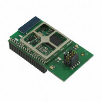
EM357-MOD-LR-ANT-TG Ember, EM357-MOD-LR-ANT-TG Datasheet - Page 140

EM357-MOD-LR-ANT-TG
Manufacturer Part Number
EM357-MOD-LR-ANT-TG
Description
MODULE EM357 PA/LNA W/ANT TG
Manufacturer
Ember
Specifications of EM357-MOD-LR-ANT-TG
Frequency
2.4GHz
Data Rate - Maximum
250kbps
Modulation Or Protocol
802.15.4 Zigbee
Voltage - Supply
2.1 V ~ 3.6 V
Current - Receiving
25mA
Current - Transmitting
42mA
Data Interface
PCB, Surface Mount
Memory Size
192kB Flash, 12kB RAM
Antenna Connector
On-Board, Chip
Operating Temperature
-40°C ~ 85°C
Package / Case
Module
Lead Free Status / RoHS Status
Lead free / RoHS Compliant
Power - Output
-
Applications
-
Sensitivity
-
Other names
636-1020
- Current page: 140 of 245
- Download datasheet (12Mb)
The TIMx_CCRy registers can be programmed with or without buffer registers using the TIM_OCyBE bit in the
TIMx_CCMR1 register.
In output compare mode, the UEV has no effect on OCyREF or the OCy output. The timing resolution is one
count of the counter. Output compare mode can also be used to output a single pulse (in one pulse mode).
Procedure:
1. Select the counter clock (internal, external, and prescaler).
2. Write the desired data in the TIMx_ARR and TIMx_CCRy registers.
3. Set the INT_TIMCCyIF bit in INT_TIMxCFG if an interrupt request is to be generated.
4. Select the output mode. For example, you must write TIM_OCyM = 011, TIM_OCyBE = 0, TIM_CCyP = 0 and
5. Enable the counter: Set the TIM_CEN bit in the TIMx_CR1 register.
To control the output waveform, software can update the TIMx_CCRy register at any time, provided that the
buffer register is not enabled (TIM_OCyBE = 0). Otherwise TIMx_CCRy shadow register is updated only at the
next UEV. An example is given in Figure 9-21.
9.3.9
Pulse width modulation mode allows you to generate a signal with a frequency determined by the value of the
TIMx_ARR register, and a duty cycle determined by the value of the TIMx_CCRy register.
PWM mode can be selected independently on each channel (one PWM per OCy output) by writing 110 (PWM
mode 1) or 111 (PWM mode 2) in the TIM_OCyM bits in the TIMx_CCMR1 register. The corresponding buffer
register must be enabled by setting the TIM_OCyBE bit in the TIMx_CCMR1 register. Finally, in up-counting or
center-aligned mode the auto-reload buffer register must be enabled by setting the TIM_ARBE bit in the
TIMx_CR1 register.
Sets a flag in the interrupt flag register (the INT_TIMCCyIF bit in the INT_TIMxFLAG register).
Generates an interrupt if the corresponding interrupt mask is set (the TIM_CCyIF bit in the INT_TIMxCFG
register).
TIM_CCyE = 1 to toggle the OCy output pin when TIMx_CNT matches TIMx_CCRy, TIMx_CCRy buffer is not
used, OCy is enabled and active high.
PWM Mode
Figure 9-21. Output Compare Mode, Toggle on OC1
Final
9-16
120-035X-000G
Related parts for EM357-MOD-LR-ANT-TG
Image
Part Number
Description
Manufacturer
Datasheet
Request
R

Part Number:
Description:
MODULE EM357 NO PA/LNA W/ANT TG
Manufacturer:
Ember
Datasheet:

Part Number:
Description:
MODULE EM357 NO PA/LNA W/RF CONN
Manufacturer:
Ember
Datasheet:

Part Number:
Description:
MODULE EM357 PA/LNA W/RF CONN
Manufacturer:
Ember
Datasheet:

Part Number:
Description:
KIT DEV EMBER ZIGBEE W/PCWH
Manufacturer:
Custom Computer Services Inc (CCS)

Part Number:
Description:
PROGRAMMER USB FLASH EM250/260
Manufacturer:
Ember
Datasheet:

Part Number:
Description:
IC ZIGBEE SYSTEM-ON-CHIP 40-QFN
Manufacturer:
Ember
Datasheet:

Part Number:
Description:
IC ZIGBEE SYSTEM-ON-CHIP 48-QFN
Manufacturer:
Ember
Datasheet:

Part Number:
Description:
IC RF TXRX ZIGBEE 128KB 48QFN
Manufacturer:
Ember
Datasheet:

Part Number:
Description:
IC RF TXRX ZIGBEE 192KB 48QFN
Manufacturer:
Ember
Datasheet:

Part Number:
Description:
INSIGHT ADAPTER FOR EM2XX
Manufacturer:
Ember
Datasheet:

Part Number:
Description:
IAR EWARM LICENCE FOR EM35X
Manufacturer:
Ember
Datasheet:

Part Number:
Description:
KIT EVAL EM250 RF TEST
Manufacturer:
Ember
Datasheet:

Part Number:
Description:
INSIGHT ADAPTER 3 FOR EM35X
Manufacturer:
Ember
Datasheet:

Part Number:
Description:
EM250 RCM BOARD
Manufacturer:
Ember
Datasheet:

Part Number:
Description:
EM35X BREAKOUT BOARD
Manufacturer:
Ember
Datasheet:


