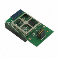
EM357-MOD-LR-ANT-TG Ember, EM357-MOD-LR-ANT-TG Datasheet - Page 48

EM357-MOD-LR-ANT-TG
Manufacturer Part Number
EM357-MOD-LR-ANT-TG
Description
MODULE EM357 PA/LNA W/ANT TG
Manufacturer
Ember
Specifications of EM357-MOD-LR-ANT-TG
Frequency
2.4GHz
Data Rate - Maximum
250kbps
Modulation Or Protocol
802.15.4 Zigbee
Voltage - Supply
2.1 V ~ 3.6 V
Current - Receiving
25mA
Current - Transmitting
42mA
Data Interface
PCB, Surface Mount
Memory Size
192kB Flash, 12kB RAM
Antenna Connector
On-Board, Chip
Operating Temperature
-40°C ~ 85°C
Package / Case
Module
Lead Free Status / RoHS Status
Lead free / RoHS Compliant
Power - Output
-
Applications
-
Sensitivity
-
Other names
636-1020
- Current page: 48 of 245
- Download datasheet (12Mb)
Table 6-9 contains the specification for the low frequency crystal oscillator.
6.3.5
The EM35x has two switching mechanisms for the main system clock, providing four clock modes. Table 6-10
shows these clock modes and how they affect the internal clocks.
The register bit OSC24M_CTRL_OSC24M_SEL in the OSC24M_CTRL register switches between the high-
frequency RC oscillator (OSCHF) and the high-frequency crystal oscillator (OSC24M) as the main system clock
(SYSCLK). The peripheral clock (PCLK) is always half the frequency of SYSCLK.
The register bit CPU_CLKSEL_FIELD in the CPU_CLKSEL register switches between PCLK and SYSCLK to produce
the ARM
higher PCLK frequency, 24 MHz, to give higher processing performance for all applications and improved duty
cycling for applications using sleep modes.
In addition to these modes, further automatic control is invoked by hardware when flash programming is
enabled. To ensure accuracy of the flash controller’s timers, the FCLK frequency is forced to 12 MHz during
flash programming and erase operations.
OSC24M_CTRL_
Parameter
Frequency
Accuracy
Load capacitance OSC32A
Load capacitance OSC32B
Crystal ESR
Start-up time
Current consumption
OSC24M_SEL
1 (OSC24M)
1 (OSC24M)
0 (OSCHF)
0 (OSCHF)
®
Clock Switching
Cortex
TM
-M3 CPU clock (FCLK). The default and preferred mode of operation is to run the CPU at the
CPU_CLKSEL_FI
0 (Normal CPU)
0 (Normal CPU)
1 (Fast CPU)
1 (Fast CPU)
Table 6-9. Low-Frequency Crystal Oscillator Specification
ELD
Test conditions
Initial, temperature, and
ageing
At 25°C, VDD_PADS=3.0 V
Table 6-10. System Clock Modes
SYSCLK
12 MHz
12 MHz
24 MHz
24 MHz
Final
6-10
12 MHz
12 MHz
PCLK
6 MHz
6 MHz
Flash Program/Erase
-100
Min
12 MHz
12 MHz
24 MHz
Inactive
6 MHz
32.768
EM351 / EM357
Typ
27
18
FCLK
Flash Program/Erase
+100
Max
100
0.5
2
12 MHz
12 MHz
12 MHz
12 MHz
Active
120-035X-000G
Unit
ppm
kHz
kΩ
pF
pF
μA
s
Related parts for EM357-MOD-LR-ANT-TG
Image
Part Number
Description
Manufacturer
Datasheet
Request
R

Part Number:
Description:
MODULE EM357 NO PA/LNA W/ANT TG
Manufacturer:
Ember
Datasheet:

Part Number:
Description:
MODULE EM357 NO PA/LNA W/RF CONN
Manufacturer:
Ember
Datasheet:

Part Number:
Description:
MODULE EM357 PA/LNA W/RF CONN
Manufacturer:
Ember
Datasheet:

Part Number:
Description:
KIT DEV EMBER ZIGBEE W/PCWH
Manufacturer:
Custom Computer Services Inc (CCS)

Part Number:
Description:
PROGRAMMER USB FLASH EM250/260
Manufacturer:
Ember
Datasheet:

Part Number:
Description:
IC ZIGBEE SYSTEM-ON-CHIP 40-QFN
Manufacturer:
Ember
Datasheet:

Part Number:
Description:
IC ZIGBEE SYSTEM-ON-CHIP 48-QFN
Manufacturer:
Ember
Datasheet:

Part Number:
Description:
IC RF TXRX ZIGBEE 128KB 48QFN
Manufacturer:
Ember
Datasheet:

Part Number:
Description:
IC RF TXRX ZIGBEE 192KB 48QFN
Manufacturer:
Ember
Datasheet:

Part Number:
Description:
INSIGHT ADAPTER FOR EM2XX
Manufacturer:
Ember
Datasheet:

Part Number:
Description:
IAR EWARM LICENCE FOR EM35X
Manufacturer:
Ember
Datasheet:

Part Number:
Description:
KIT EVAL EM250 RF TEST
Manufacturer:
Ember
Datasheet:

Part Number:
Description:
INSIGHT ADAPTER 3 FOR EM35X
Manufacturer:
Ember
Datasheet:

Part Number:
Description:
EM250 RCM BOARD
Manufacturer:
Ember
Datasheet:

Part Number:
Description:
EM35X BREAKOUT BOARD
Manufacturer:
Ember
Datasheet:


