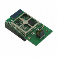
EM357-MOD-LR-ANT-TG Ember, EM357-MOD-LR-ANT-TG Datasheet - Page 139

EM357-MOD-LR-ANT-TG
Manufacturer Part Number
EM357-MOD-LR-ANT-TG
Description
MODULE EM357 PA/LNA W/ANT TG
Manufacturer
Ember
Specifications of EM357-MOD-LR-ANT-TG
Frequency
2.4GHz
Data Rate - Maximum
250kbps
Modulation Or Protocol
802.15.4 Zigbee
Voltage - Supply
2.1 V ~ 3.6 V
Current - Receiving
25mA
Current - Transmitting
42mA
Data Interface
PCB, Surface Mount
Memory Size
192kB Flash, 12kB RAM
Antenna Connector
On-Board, Chip
Operating Temperature
-40°C ~ 85°C
Package / Case
Module
Lead Free Status / RoHS Status
Lead free / RoHS Compliant
Power - Output
-
Applications
-
Sensitivity
-
Other names
636-1020
- Current page: 139 of 245
- Download datasheet (12Mb)
Figure 9-20 illustrates this example.
9.3.7
In output mode (CCyS bits = 00 in the TIMx_CCMR1 register), software can force each output compare signal
(OCyREF and then OCy) to an active or inactive level independently of any comparison between the output
compare register and the counter.
To force an output compare signal (OCyREF/OCy) to its active level, write 101 in the TIM_OCyM bits in the
corresponding TIMx_CCMR1 register. OCyREF is forced high (OCyREF is always active high) and OCy gets the
opposite value to the TIM_CCyP polarity bit. For example, TIM_CCyP = 0 defines OCy as active high, so when
OCyREF is active, OCy is also set to a high level.
The OCyREF signal can be forced low by writing the TIM_OCyM bits to 100 in the TIMx_CCMR1 register.
The comparison between the TIMx_CCRy shadow register and the counter is still performed and allows the
INT_TIMxCCRyIF flag to be set. Interrupt requests can be sent accordingly. This is described in the output
compare mode section.
9.3.8
This mode is used to control an output waveform or to indicate when a period of time has elapsed.
When a match is found between the capture/compare register and the counter, the output compare function:
Select the active input for TIMx_CCR2by writing the TIM_CC2S bits to 10 in the TIMx_CCMR1 register (TI1
selected).
Select the active polarity for TI1FP2 (used for capture in the TIMx_CCR2) by writing the TIM_CC2P bit to 1
(active on falling edge).
Select the valid trigger input by writing the TIM_TS bits to 101 in the TIMx_SMCR register (TI1FP1
selected).
Configure the slave mode controller in reset mode by writing the TIM_SMS bits to 100 in the TIMx_SMCR
register.
Enable the captures by writing the TIM_CC1E and TIM_CC2E bits to 1 in the TIMx_CCER register.
Assigns the corresponding output pin to a programmable value defined by the output compare mode (the
TIM_OCyM bits in the TIMx_CCMR1 register) and the output polarity (the TIM_CCyP bit in the TIMx_CCER
register). The output can be frozen (TIM_OCyM = 000), be set active (TIM_OCyM = 001), be set inactive
(TIM_OCyM = 010), or can toggle (TIM_OCyM = 011) on the match.
Forced Output Mode
Output Compare Mode
Figure 9-20. PWM Input Mode Timing
Final
9-15
120-035X-000G
Related parts for EM357-MOD-LR-ANT-TG
Image
Part Number
Description
Manufacturer
Datasheet
Request
R

Part Number:
Description:
MODULE EM357 NO PA/LNA W/ANT TG
Manufacturer:
Ember
Datasheet:

Part Number:
Description:
MODULE EM357 NO PA/LNA W/RF CONN
Manufacturer:
Ember
Datasheet:

Part Number:
Description:
MODULE EM357 PA/LNA W/RF CONN
Manufacturer:
Ember
Datasheet:

Part Number:
Description:
KIT DEV EMBER ZIGBEE W/PCWH
Manufacturer:
Custom Computer Services Inc (CCS)

Part Number:
Description:
PROGRAMMER USB FLASH EM250/260
Manufacturer:
Ember
Datasheet:

Part Number:
Description:
IC ZIGBEE SYSTEM-ON-CHIP 40-QFN
Manufacturer:
Ember
Datasheet:

Part Number:
Description:
IC ZIGBEE SYSTEM-ON-CHIP 48-QFN
Manufacturer:
Ember
Datasheet:

Part Number:
Description:
IC RF TXRX ZIGBEE 128KB 48QFN
Manufacturer:
Ember
Datasheet:

Part Number:
Description:
IC RF TXRX ZIGBEE 192KB 48QFN
Manufacturer:
Ember
Datasheet:

Part Number:
Description:
INSIGHT ADAPTER FOR EM2XX
Manufacturer:
Ember
Datasheet:

Part Number:
Description:
IAR EWARM LICENCE FOR EM35X
Manufacturer:
Ember
Datasheet:

Part Number:
Description:
KIT EVAL EM250 RF TEST
Manufacturer:
Ember
Datasheet:

Part Number:
Description:
INSIGHT ADAPTER 3 FOR EM35X
Manufacturer:
Ember
Datasheet:

Part Number:
Description:
EM250 RCM BOARD
Manufacturer:
Ember
Datasheet:

Part Number:
Description:
EM35X BREAKOUT BOARD
Manufacturer:
Ember
Datasheet:


