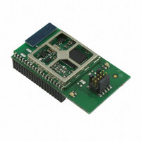
EM357-MOD-LR-ANT-TG Ember, EM357-MOD-LR-ANT-TG Datasheet - Page 165

EM357-MOD-LR-ANT-TG
Manufacturer Part Number
EM357-MOD-LR-ANT-TG
Description
MODULE EM357 PA/LNA W/ANT TG
Manufacturer
Ember
Specifications of EM357-MOD-LR-ANT-TG
Frequency
2.4GHz
Data Rate - Maximum
250kbps
Modulation Or Protocol
802.15.4 Zigbee
Voltage - Supply
2.1 V ~ 3.6 V
Current - Receiving
25mA
Current - Transmitting
42mA
Data Interface
PCB, Surface Mount
Memory Size
192kB Flash, 12kB RAM
Antenna Connector
On-Board, Chip
Operating Temperature
-40°C ~ 85°C
Package / Case
Module
Lead Free Status / RoHS Status
Lead free / RoHS Compliant
Power - Output
-
Applications
-
Sensitivity
-
Other names
636-1020
- Current page: 165 of 245
- Download datasheet (12Mb)
Bitname
TIM_OC4FE
TIM_IC4F
TIM_IC4PSC
TIM_CC4S
TIM_OC3M
TIM_OC3BE
TIM_OC3FE
TIM_IC3F
TIM_IC3PSC
Bitfield
[15:12]
[11:10]
[9:8]
[6:4]
[7:4]
[3:2]
[10]
[2]
[3
Access
RW
RW
RW
RW
RW
RW
RW
RW
RW
Description
Output Compare 4 Fast Enable. (Applies only if TIM_CC4S = 0.)
This bit speeds the effect of an event on the trigger in input on the OC4 output.
0: OC4 behaves normally depending on the counter and TIM_CCR4 values even when the
trigger is ON. The minimum delay to activate OC4 when an edge occurs on the trigger
input is 5 clock cycles.
1: An active edge on the trigger input acts like a compare match on the OC4 output. OC4
is set to the compare level independently from the result of the comparison. Delay to
sample the trigger input and to activate OC4 output is reduced to 3 clock cycles.
TIM_OC4FE acts only if the channel is configured in PWM 1 or PWM 2 mode.
Input Capture 4 Filter. (Applies only if TIM_CC4S > 0.)
This defines the frequency used to sample the TI4 input, Fsampling, and the length of the
digital filter applied to TI4. The digital filter requires N consecutive samples in the same
state before being output.
0000: Fsampling=PCLK, no filtering.
0001: Fsampling=PCLK, N=2.
0010: Fsampling=PCLK, N=4.
0011: Fsampling=PCLK, N=8.
0100: Fsampling=PCLK/2, N=6.
0101: Fsampling=PCLK/2, N=8.
0110: Fsampling=PCLK/4, N=6.
0111: Fsampling=PCLK/4, N=8.
1000: Fsampling=PCLK/8, N=6.
1001: Fsampling=PCLK/8, N=8.
1010: Fsampling=PCLK/16, N=5.
1011: Fsampling=PCLK/16, N=6.
1100: Fsampling=PCLK/16, N=8.
1101: Fsampling=PCLK/32, N=5.
1110: Fsampling=PCLK/32, N=6.
1111: Fsampling=PCLK/32, N=8.
Note: PCLK is 12 MHz when using the 24 MHz crystal oscillator, and 6 MHz using the 12 MHz
RC oscillator.
Input Capture 4 Prescaler. (Applies only if TIM_CC4S > 0.)
00: No prescaling, capture each time an edge is detected on the capture input.
01: Capture once every 2 events.
10: Capture once every 4 events.
11: Capture once every 6 events.
Capture / Compare 4 Selection.
This configures the channel as an output or an input. If an input, it selects the input
source.
00: Channel is an output.
01: Channel is an input and is mapped to TI4.
10: Channel is an input and is mapped to TI3.
11: Channel is an input and is mapped to TRGI. This mode requires an internal trigger
input selected by the TIM_TS bit in the TIMx_SMCR register.
Note: TIM_CC4S may be written only when the channel is off (TIM_CC4E = 0 in the
TIMx_CCER register).
Output Compare 3 Mode. (Applies only if TIM_CC3S = 0.)
See TIM_OC4M description above.
Output Compare 3 Buffer Enable. (Applies only if TIM_CC3S = 0.)
See TIM_OC4BE description above.
Output Compare 3 Fast Enable. (Applies only if TIM_CC3S = 0.)
See TIM_OC4FE description above.
Input Capture 3 Filter. (Applies only if TIM_CC3S > 0.)
See TIM_IC4F description above.
Input Capture 3 Prescaler. (Applies only if TIM_CC3S > 0.)
See TIM_IC4PSC description above.
Final
9-41
120-035X-000G
Related parts for EM357-MOD-LR-ANT-TG
Image
Part Number
Description
Manufacturer
Datasheet
Request
R

Part Number:
Description:
MODULE EM357 NO PA/LNA W/ANT TG
Manufacturer:
Ember
Datasheet:

Part Number:
Description:
MODULE EM357 NO PA/LNA W/RF CONN
Manufacturer:
Ember
Datasheet:

Part Number:
Description:
MODULE EM357 PA/LNA W/RF CONN
Manufacturer:
Ember
Datasheet:

Part Number:
Description:
KIT DEV EMBER ZIGBEE W/PCWH
Manufacturer:
Custom Computer Services Inc (CCS)

Part Number:
Description:
PROGRAMMER USB FLASH EM250/260
Manufacturer:
Ember
Datasheet:

Part Number:
Description:
IC ZIGBEE SYSTEM-ON-CHIP 40-QFN
Manufacturer:
Ember
Datasheet:

Part Number:
Description:
IC ZIGBEE SYSTEM-ON-CHIP 48-QFN
Manufacturer:
Ember
Datasheet:

Part Number:
Description:
IC RF TXRX ZIGBEE 128KB 48QFN
Manufacturer:
Ember
Datasheet:

Part Number:
Description:
IC RF TXRX ZIGBEE 192KB 48QFN
Manufacturer:
Ember
Datasheet:

Part Number:
Description:
INSIGHT ADAPTER FOR EM2XX
Manufacturer:
Ember
Datasheet:

Part Number:
Description:
IAR EWARM LICENCE FOR EM35X
Manufacturer:
Ember
Datasheet:

Part Number:
Description:
KIT EVAL EM250 RF TEST
Manufacturer:
Ember
Datasheet:

Part Number:
Description:
INSIGHT ADAPTER 3 FOR EM35X
Manufacturer:
Ember
Datasheet:

Part Number:
Description:
EM250 RCM BOARD
Manufacturer:
Ember
Datasheet:

Part Number:
Description:
EM35X BREAKOUT BOARD
Manufacturer:
Ember
Datasheet:


