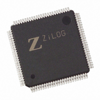
Z8018233ASG Zilog, Z8018233ASG Datasheet - Page 10

Z8018233ASG
Manufacturer Part Number
Z8018233ASG
Description
IC 33MHZ STATIC MIMIC 100-LQFP
Manufacturer
Zilog
Datasheet
1.Z8018233FSG.pdf
(109 pages)
Specifications of Z8018233ASG
Processor Type
Z180
Features
Smart Peripheral Controller
Speed
33MHz
Voltage
5V
Mounting Type
Surface Mount
Package / Case
100-LQFP
Processor Series
Z8018xx
Core
Z80
Data Bus Width
8 bit
Program Memory Type
ROMLess
Interface Type
UART
Maximum Clock Frequency
33 MHz
Number Of Programmable I/os
24
Number Of Timers
2
Operating Supply Voltage
4.5 V to 5.5 V
Maximum Operating Temperature
+ 70 C
Mounting Style
SMD/SMT
Minimum Operating Temperature
0 C
Lead Free Status / RoHS Status
Lead free / RoHS Compliant
Available stocks
Company
Part Number
Manufacturer
Quantity
Price
Zilog
EMULATION SIGNALS
EV1, EV2. Emulation Select (input). These two pins
determine the emulation mode of the Z180 MPU (Table 1).
SYSTEM CONTROL SIGNALS
3-10
ST. Status (output, active High). This signal is used with the
/M1 and /HALT output to decode the status of the CPU
machine cycle. If unused, this pin should be pulled to V
/RESET. Reset Signal (input, active Low) . /RESET signal is
used for initializing the MPU and other devices in the
system. It must be kept in the active state for a period of at
least three system clock cycles.
IEI. Interrupt Enable Signal (input, active High). IEI is used
with the IEO to form a priority daisy chain when there is
more than one interrupt-driven peripheral.
IEO. Interrupt Enable Output Signal (output, active High).
In the daisy-chain interrupt control, IEO controls the interrupt
of external peripherals. IEO is active when IEI is 1 and the
CPU is not servicing an interrupt from the on-chip
peripherals. This pin is multiplexed with /IOCS on the
/IOCS/IEO pin. The /IOCS function is the default on Power
On or Reset conditions and is changed by programming
bit 2 in the Interrupt Edge/Pin MUX Register.
/IOCS. Auxiliary Chip Select Output Signal (output, active
Low). This pin is multiplexed with /IEO on the /IOCS/IEO
pin. /IOCS is an auxiliary chip select that decodes A7, A6,
/IORQ, /M1 and effectively decodes the address space
xx80H to xxBFH for I/O transactions. A15 through A8 are
not decoded so that the chip select is active in all pages of
I/O address space. The /IOCS function is the default on the
/IOCS/IEO pin after Power On or Reset conditions and is
changed by programming bit 2 in the Interrupt Edge/Pin
MUX Register.
Mode
0
1
2
3
EV2
0
0
1
1
P R E L I M I N A R Y
PS009801-0301
Table 1. Evaluation Modes
EV1
0
1
0
1
DD
.
/RAMCS. RAM Chip Select (output, active Low) . Signal
used to access RAM based upon the Address and the
RAMLBR and RAMUBR registers and /MREQ.
/ROMCS. ROM Chip Select (output, active Low). Signal
used to access ROM based upon the address and the
ROMBR register and /MREQ.
E. Enable Clock (output, active High). Synchronous
machine cycle clock output during bus transactions.
XTAL. Crystal (input, active High). Crystal oscillator
connection. This pin should be left open if an external clock
is used instead of a crystal. The oscillator input is not a TTL
level (reference DC characteristics).
EXTAL. External Clock/Crystal (input, active High). Crystal
oscillator connections to an external clock can be input to
the Z80180 on this pin when a crystal is not used. This input
is Schmitt triggered.
PHI. System Clock (output, active High). The output is
used as a reference clock for the MPU and the external
system. The frequency of this output is reflective of the
functional speed of the processor. In clock divide-by-two
mode, the pHI frequency is half that of the crystal or input
clock. If divide-by-one mode is enabled, the PHI frequency
is equivalent to that of crystal or input frequency. The PHI
frequency is also fed to the ESCC core. If running over 20
MHz (5V) or 10 MHz (3V) the PHI-ESCC frequency divider
should be enabled to divide the PHI clock by two prior to
feeding into the ESCC core.
Description
Normal mode, on-chip Z180 bus master
Emulation Adapter Mode
Emulator Probe Mode
Reserved for Test
Z
ILOG
I
NTELLIGENT
DS971820600
Z80182/Z8L182
P
ERIPHERAL


