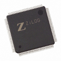
Z8018233ASG Zilog, Z8018233ASG Datasheet - Page 78

Z8018233ASG
Manufacturer Part Number
Z8018233ASG
Description
IC 33MHZ STATIC MIMIC 100-LQFP
Manufacturer
Zilog
Datasheet
1.Z8018233FSG.pdf
(109 pages)
Specifications of Z8018233ASG
Processor Type
Z180
Features
Smart Peripheral Controller
Speed
33MHz
Voltage
5V
Mounting Type
Surface Mount
Package / Case
100-LQFP
Processor Series
Z8018xx
Core
Z80
Data Bus Width
8 bit
Program Memory Type
ROMLess
Interface Type
UART
Maximum Clock Frequency
33 MHz
Number Of Programmable I/os
24
Number Of Timers
2
Operating Supply Voltage
4.5 V to 5.5 V
Maximum Operating Temperature
+ 70 C
Mounting Style
SMD/SMT
Minimum Operating Temperature
0 C
Lead Free Status / RoHS Status
Lead free / RoHS Compliant
Available stocks
Company
Part Number
Manufacturer
Quantity
Price
Zilog
Z80182/Z8L182 MIMIC DMA CONSIDERATIONS
Mode 0 Normal Mode
This is the normal operating mode for the Z80182/Z8L182.
Mode 1 Emulation Adapter Mode
The Emulation Adaptor Mode enables system development
for the Z182 with a readily available Z180 emulator. The
Emulator provides the Z180
functions to the target system, with their signals passing
EMULATION MODES
The Z80182/Z8L182 provides four modes of operation.
The modes are selected by the EV1 and EV2 pins. These
four modes allow the system development and commercial
3-78
For the PC Interface, the 16550 device has two modes of
operation that need to be supported by the MIMIC. In
single transfer mode, the DMA request line for the receiver
goes active whenever there is at least one character in the
RCVR FIFO. For the transmitter, the DMA request line is
active on an empty XMIT FIFO and inactive on non-empty.
In multi-transfer mode, the RCVR DMA goes active at the
trigger level and inactive on RCVR FIFO empty. The XMIT
DMA is active on non-full XMIT FIFO and inactive on a full
XMIT FIFO.
Bit 3 in the FCR controls the DMA mode for the PC
interface. If a 1 is programmed into this bit, multi-byte DMA
is enabled. A 0 in this bit (default) enables single byte
DMA.
Mode 0
Mode 1
Mode 2
Mode 3
™
MPU and Z180 peripheral
Table 20. EV2 and EV1, Emulation Mode Control
EV2
0
0
1
1
P R E L I M I N A R Y
PS009801-0301
EV1
0
1
0
1
As specified, the 16550 does not have any means of
handling the error status bits in the FIFO in this multi-
transfer mode. Such DMA transfers would require blocks
with some checksum or other error checking scheme.
For the MPU interface, the DMA is controlled by a non-
empty transmit FIFO and by a non-full receive FIFO
conditions (THRE and the DR bits in the LSR). If the delay
timers are enabled, the respective shadow bits are used
for DMA control. The effect of the DMA logic is to request
DMA service when at least one byte of data is available to
be read or written to the FIFO’s by the Z180. The Z180's
DMA channel can be programmed to trigger on edge or on
level.
production to be done with the same device. The four
emulation modes are shown in Table 20.
through the emulation adapter. In Emulation Adaptor Mode
the Z182s, Z180 MPU and Z180 peripheral signals are tri-
state or physically disconnected. The Z182 continues to
provide its ESCC, MIMIC, chip select, and Port functions
and signals to the target system. The Mode 1 effects on the
Z182 are shown in Table 21. Note that INT1-2 Edge Detect
Logic cannot be used in Emulation Adaptor EV Mode 2.
EV Description
Emulation Adapter Mode
Emulator Probe Mode
Normal Mode, on-chip Z180 bus master
RESERVED, for Test Use Only
Z
ILOG
I
NTELLIGENT
DS971820600
Z80182/Z8L182
P
ERIPHERAL


