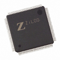
Z8018233ASG Zilog, Z8018233ASG Datasheet - Page 64

Z8018233ASG
Manufacturer Part Number
Z8018233ASG
Description
IC 33MHZ STATIC MIMIC 100-LQFP
Manufacturer
Zilog
Datasheet
1.Z8018233FSG.pdf
(109 pages)
Specifications of Z8018233ASG
Processor Type
Z180
Features
Smart Peripheral Controller
Speed
33MHz
Voltage
5V
Mounting Type
Surface Mount
Package / Case
100-LQFP
Processor Series
Z8018xx
Core
Z80
Data Bus Width
8 bit
Program Memory Type
ROMLess
Interface Type
UART
Maximum Clock Frequency
33 MHz
Number Of Programmable I/os
24
Number Of Timers
2
Operating Supply Voltage
4.5 V to 5.5 V
Maximum Operating Temperature
+ 70 C
Mounting Style
SMD/SMT
Minimum Operating Temperature
0 C
Lead Free Status / RoHS Status
Lead free / RoHS Compliant
Available stocks
Company
Part Number
Manufacturer
Quantity
Price
Zilog
IUS/IP Register
The IUS/IP Register is used by the Z180
the source of the interrupt. This register will have the
appropriate bit set when an interrupt occurs.
Bit 7 Interrupt Under Service (Read/Write)
This bit represents a logical OR of each individual IUS bit
for the internal MIMIC interrupt daisy chain. An IUS bit is set
when an interrupt is registered (IP set) and enabled (IE
set), the incoming IEI daisy chain is active (chain enabled)
and an interrupt acknowledge cycle is entered. By writing
a 1 to this bit the highest priority IUS bit that is set will be
reset. Writing a 0 to this bit has no effect.
This should be done at the end of every MIMIC Interrupt
Service routine.
Bit 6 Transmit Holding Register Written (Read Only)
This bit is set when the PC/XT/AT writes to the Transmit
Holding Register. It is reset when the Z180 MPU reads the
Transmit Holding Register. In FIFO mode, this bit is set
when the trigger level is reached (4,8,14 bytes available).
Note: The THR bit is set (interrupts) when the transmitter
FIFO reaches the data available trigger level set in the MPU
FCR control register. The bit and interrupt source is cleared
when the number of data bytes falls below the set trigger
level.
3-64
D7
0
D6 D5 D4 D3 D2 D1 D0
0
0
0
(Z180 MPU, Address xxFEH)
Figure 61. IUS/IP Register
0
0
0
0
Interrupt Pending
6 THR Write
5 TTO Transmitter Timeout
4 RBR Read
3 MCR Write
2 LCR Write
1 DLL Write
1 DLM Write
0 FCR Write or Tx Overrun
Interrupt Under Service (RD)
Reset Highest IUS (WR)
™
MPU to determine
P R E L I M I N A R Y
PS009801-0301
Bit 5 Transmitter Timeout with Data in FIFO (Read
Only)
This bit is set when the transmitter FIFO has been idle (no
read or write and timer decrements to zero) with data bytes
below the trigger level. It is cleared when the FIFO is read
or written.
Bit 4 Receive Buffer Read (Read Only)
This bit is set when the PC/XT/AT reads the Receive Buffer
Register. It is reset when the Z180 MPU writes to the
Receive Buffer Register. In FIFO mode, this bit is set upon
the PC reading all the data in the receive FIFO. Note: RBR
is set and interrupts when the receive FIFO has been
emptied by the PC. This bit and interrupt are cleared when
one or more bytes are written into the receive FIFO by the
MPU.
Bit 3 Modem Control Register Write (Read Only)
This bit is set when the PC/XT/AT writes to the Modem
Control Register. It is reset when the Z180
Modem Control Register.
Bit 2 Line Control Register Write (Read Only)
This bit is set when the PC/XT/AT writes to the Line Control
Register. It is reset when the Z180 MPU reads the Line
Control Register.
Bit 1 Divisor Latch LS/MS Write (Read Only)
This bit is set when the PC/XT/AT writes to the Divisor Latch
Least Significant or Most Significant bytes. It is reset when
the PC reads the LS/MS register(s). To determine which
byte(s) have been written, the Z180 must read either LS or
MS locations and then repoll this bit. If only one location is
interrupting, the interrupt is cleared when that location is
read by the Z180.
Bit 0 FIFO Control Register Write (Read Only)
This bit is set when the PC/XT/AT writes to the FCR. This bit
is also set when Transmit occurs. It is reset when the Z180
MPU reads this register.
Z
ILOG
I
NTELLIGENT
™
MPU reads the
DS971820600
Z80182/Z8L182
P
ERIPHERAL


