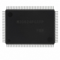
M30624FGAFP#U3 Renesas Electronics America, M30624FGAFP#U3 Datasheet - Page 86

M30624FGAFP#U3
Manufacturer Part Number
M30624FGAFP#U3
Description
IC M16C MCU FLASH 100QFP
Manufacturer
Renesas Electronics America
Series
M16C™ M16C/60r
Datasheets
1.M30622SAFPU5.pdf
(277 pages)
2.M30622SAFPU5.pdf
(617 pages)
3.M30622SAFPU5.pdf
(308 pages)
Specifications of M30624FGAFP#U3
Core Processor
M16C/60
Core Size
16-Bit
Speed
16MHz
Connectivity
SIO, UART/USART
Peripherals
DMA, PWM, WDT
Number Of I /o
85
Program Memory Size
256KB (256K x 8)
Program Memory Type
FLASH
Ram Size
20K x 8
Voltage - Supply (vcc/vdd)
4.2 V ~ 5.5 V
Data Converters
A/D 10x10b, D/A 2x8b
Oscillator Type
Internal
Operating Temperature
-40°C ~ 85°C
Package / Case
100-QFP
For Use With
867-1000 - KIT QUICK START RENESAS 62PM3062PT3-CPE-3 - EMULATOR COMPACT M16C/62P/30P
Lead Free Status / RoHS Status
Lead free / RoHS Compliant
Eeprom Size
-
Available stocks
Company
Part Number
Manufacturer
Quantity
Price
Part Number:
M30624FGAFP#U3M30624FGAFP#D3
Manufacturer:
Renesas Electronics America
Quantity:
10 000
Part Number:
M30624FGAFP#U3M30624FGAFP#D5
Manufacturer:
Renesas Electronics America
Quantity:
10 000
Timer A
Table 1.14.2. Timer specifications in event counter mode (when not processing two-phase pulse signal)
Note: This does not apply when the free-run function is selected.
Figure 1.14.8. Timer Ai mode register in event counter mode
(2) Event counter mode
Count source
Count operation
Divide ratio
Count start condition
Count stop condition
Interrupt request generation timing The timer overflows or underflows
TAi
TAi
Read from timer
Write to timer
Select function
In this mode, the timer counts an external signal or an internal timer’s overflow. Timers A0 and A1 can
count a single-phase external signal. Timers A2, A3, and A4 can count a single-phase and a two-phase
external signal. Table 1.14.2 lists timer specifications when counting a single-phase external signal.
Figure 1.14.8 shows the timer Ai mode register in event counter mode.
Table 1.14.3 lists timer specifications when counting a two-phase external signal. Figure 1.14.9 shows
the timer Ai mode register in event counter mode.
IN
OUT
pin function
pin function
Item
Timer Ai mode register
(When not using two-phase pulse signal processing)
b7
b6
b5
0
b4
b3
b2
• External signals input to TAi
• TB2 overflow, TAj overflow
• Up count or down count can be selected by external signal or software
• When the timer overflows or underflows, it reloads the reload register con
1/ (FFFF
1/ (n + 1) for down count
Count start flag is set (= 1)
Count start flag is reset (= 0)
Programmable I/O port or count source input
Programmable I/O port, pulse output, or up/down count select input
Count value can be read out by reading timer Ai register
• When counting stopped
• When counting in progress
• Free-run count function
• Pulse output function
b1
0 1
tents before continuing counting (Note)
When a value is written to timer Ai register, it is written to both reload register and counter
When a value is written to timer Ai register, it is written to only reload register
(Transferred to counter at next reload time)
Even when the timer overflows or underflows, the reload register content is not reloaded to it
Each time the timer overflows or underflows, the TAi
b0
Note 1: In event counter mode, the count source is selected by the event / trigger select bit
Note 2: The settings of the corresponding port register and port direction register are invalid.
Note 3: Valid only when counting an external signal.
Note 4: When an “L” signal is input to the TAi
Bit symbol
TMOD0
TMOD1
MR1
TCK0
TCK1
MR0
MR2
MR3
(addresses 0382
the upcount is activated. Set the corresponding port direction register to “0”.
16
Symbol
TAiMR(i = 0 to 4) 0396
- n + 1) for up count
Operation mode select bit
Pulse output function
select bit
Up/down switching
cause select bit
0 (Must always be “0” in event counter mode)
Invalid when not using two-phase pulse signal processing
Can be “0” or “1”
Count polarity
select bit (Note 3)
Count operation type
select bit
Bit name
16
and 0383
Address
16
to 039A
16
).
IN
0 1 : Event counter mode (Note 1)
0 : Pulse is not output
1 : Pulse is output (Note 2)
Specification
b1 b0
0 : Counts external signal's falling edge
1 : Counts external signal's rising edge
0 : Up/down flag's content
1 : TA
0 : Reload type
1 : Free-run type
16
pin (effective edge can be selected by software)
(TA
(TA
When reset
OUT
iOUT
iOUT
iOUT
00
pin, the downcount is activated. When “H”,
pin's input signal (Note 4)
16
pin is a normal port pin)
pin is a pulse output pin)
n : Set value
Function
SINGLE-CHIP 16-BIT CMOS MICROCOMPUTER
OUT
R W
R
pin’s polarity is reversed
W
M16C / 62A Group
Mitsubishi microcomputers
83


