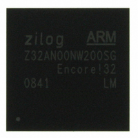
Z32AN00NW200SG Zilog, Z32AN00NW200SG Datasheet - Page 143

Z32AN00NW200SG
Manufacturer Part Number
Z32AN00NW200SG
Description
IC ARM922T MCU 200MHZ 256-BGA
Manufacturer
Zilog
Series
Encore!® 32r
Datasheet
1.Z32AN00NW200SG.pdf
(196 pages)
Specifications of Z32AN00NW200SG
Core Processor
ARM9
Core Size
16/32-Bit
Speed
200MHz
Connectivity
EBI/EMI, IrDA, SmartCard, SPI, UART/USART, USB OTG
Peripherals
DMA, LCD, Magnetic Card Reader, POR, PWM, WDT
Number Of I /o
76
Program Memory Type
ROMless
Ram Size
64K x 8
Voltage - Supply (vcc/vdd)
1.71 V ~ 3.6 V
Data Converters
A/D 4x10b
Oscillator Type
Internal
Operating Temperature
-40°C ~ 85°C
Package / Case
256-LBGA
For Use With
269-4713 - KIT DEV ENCORE 32 SERIES
Lead Free Status / RoHS Status
Lead free / RoHS Compliant
Eeprom Size
-
Program Memory Size
-
Other names
269-4717
Available stocks
Company
Part Number
Manufacturer
Quantity
Price
- Current page: 143 of 196
- Download datasheet (4Mb)
Z32AN Series Data Sheet
17.1.4.3
17.2 UART Usage
17.2.1 Control Transfers
17.2.2 Data Transfers
17.2.2.1
17.2.2.2
17.2.2.3
17.2.3 Poll Mode Transfers
DS0200-003
The specific error bits in the UARTx_LSR will only assert when the READ pointer points to the location of
the FIFO that contains the byte with an error. To insure that all bytes with errors have been removed from
the trigger level portion of the receive FIFO, software must loop on reading the LSR and RBR registers until
the ERR bit is cleared. After the ERR bit is cleared, the DMA request is re-enabled. Any remaining valid data
in the receive FIFO will then be handled by the DMA. An alternative is for software to assert the
CLRRXF bit of the UARTx_FCR register which will empty the receive data and error FIFO.
The modem status interrupt is generated if there is any change in state of the modem status inputs to the
UART. This interrupt is cleared when the processor reads UARTx_MSR.
Following is the standard sequence of events that occur in the Z32AN SOC using the UART:
The data transfer baud rate is determined and the BRG is configured to generate a 16X clock frequency.
Interrupts are disabled and the communication control parameters are programmed in UARTx_LCR. FIFO
configuration is determined and the receive trigger levels are set in UARTx_FCR. Status registers,
UARTx_LSR and UARTx_MSR, are cleared. Interrupts are enabled (except for the transmit interrupt) and
the application is ready to use the module for transmission/reception.
To control and check modem status, software writes to UARTx_MCR and reading UARTx_MSR.
To transmit data, software enables the transmit interrupt. An interrupt is immediately expected in response.
Software reads UARTx_IIR and determines that the interrupt occurs due to an empty UARTx_THR register,
and writes data bytes to UARTx_THR.
The number of bytes that the application writes depends on whether or not the FIFO is enabled. If the FIFO
is enabled, software may write 16 bytes at a time. If not, software can write one byte at a time. As a result of
the first write, the interrupt is deactivated. When a new interrupt is generated, software repeats the process
until it exhausts all data for transmission.
The receiver is always enabled, checking for the start bit on RXD. When an interrupt is generated, software
reads UARTx_IIR to determine the cause.
If the cause is a line status interrupt, software reads UARTx_LSR and reads the data byte. If the cause is a
receive-data-ready condition, software alternately reads UARTx_LSR and UARTx_RBR registers and
removes all received data bytes. It reads UARTx_LSR before reading the UARTx_RBR register to determine
any errors in the received data.
When interrupts are disabled, all data transfers are referred as poll mode transfers. In poll mode transfers,
the application must continually poll the UARTx_LSR register to transmit or receive data without enabling
the interrupts. The same holds true for the UARTx_MSR register. If the interrupts are not enabled, the data
in the UARTx_IIR register cannot be used to determine the cause of interrupt.
Modem Status Interrupt
Control/Check Modem Status
Data Transfers—Transmit with Interrupt
Data Transfers—Receive with Interrupt
1.
2.
3.
Module Reset. Upon reset, internal registers are at their defaults, and the FIFOs are flushed.
Control Transfers
Data Transfers
Page 130
Related parts for Z32AN00NW200SG
Image
Part Number
Description
Manufacturer
Datasheet
Request
R

Part Number:
Description:
Communication Controllers, ZILOG INTELLIGENT PERIPHERAL CONTROLLER (ZIP)
Manufacturer:
Zilog, Inc.
Datasheet:

Part Number:
Description:
KIT DEV FOR Z8 ENCORE 16K TO 64K
Manufacturer:
Zilog
Datasheet:

Part Number:
Description:
KIT DEV Z8 ENCORE XP 28-PIN
Manufacturer:
Zilog
Datasheet:

Part Number:
Description:
DEV KIT FOR Z8 ENCORE 8K/4K
Manufacturer:
Zilog
Datasheet:

Part Number:
Description:
KIT DEV Z8 ENCORE XP 28-PIN
Manufacturer:
Zilog
Datasheet:

Part Number:
Description:
DEV KIT FOR Z8 ENCORE 4K TO 8K
Manufacturer:
Zilog
Datasheet:

Part Number:
Description:
CMOS Z8 microcontroller. ROM 16 Kbytes, RAM 256 bytes, speed 16 MHz, 32 lines I/O, 3.0V to 5.5V
Manufacturer:
Zilog, Inc.
Datasheet:

Part Number:
Description:
Low-cost microcontroller. 512 bytes ROM, 61 bytes RAM, 8 MHz
Manufacturer:
Zilog, Inc.
Datasheet:

Part Number:
Description:
Z8 4K OTP Microcontroller
Manufacturer:
Zilog, Inc.
Datasheet:

Part Number:
Description:
CMOS SUPER8 ROMLESS MCU
Manufacturer:
Zilog, Inc.
Datasheet:

Part Number:
Description:
SL1866 CMOSZ8 OTP Microcontroller
Manufacturer:
Zilog, Inc.
Datasheet:

Part Number:
Description:
SL1866 CMOSZ8 OTP Microcontroller
Manufacturer:
Zilog, Inc.
Datasheet:

Part Number:
Description:
OTP (KB) = 1, RAM = 125, Speed = 12, I/O = 14, 8-bit Timers = 2, Comm Interfaces Other Features = Por, LV Protect, Voltage = 4.5-5.5V
Manufacturer:
Zilog, Inc.
Datasheet:

Part Number:
Description:
Manufacturer:
Zilog, Inc.
Datasheet:


