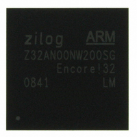
Z32AN00NW200SG Zilog, Z32AN00NW200SG Datasheet - Page 171

Z32AN00NW200SG
Manufacturer Part Number
Z32AN00NW200SG
Description
IC ARM922T MCU 200MHZ 256-BGA
Manufacturer
Zilog
Series
Encore!® 32r
Datasheet
1.Z32AN00NW200SG.pdf
(196 pages)
Specifications of Z32AN00NW200SG
Core Processor
ARM9
Core Size
16/32-Bit
Speed
200MHz
Connectivity
EBI/EMI, IrDA, SmartCard, SPI, UART/USART, USB OTG
Peripherals
DMA, LCD, Magnetic Card Reader, POR, PWM, WDT
Number Of I /o
76
Program Memory Type
ROMless
Ram Size
64K x 8
Voltage - Supply (vcc/vdd)
1.71 V ~ 3.6 V
Data Converters
A/D 4x10b
Oscillator Type
Internal
Operating Temperature
-40°C ~ 85°C
Package / Case
256-LBGA
For Use With
269-4713 - KIT DEV ENCORE 32 SERIES
Lead Free Status / RoHS Status
Lead free / RoHS Compliant
Eeprom Size
-
Program Memory Size
-
Other names
269-4717
Available stocks
Company
Part Number
Manufacturer
Quantity
Price
Z32AN Series Data Sheet
19.5 Host Mode Operation
19.5.1 Discover a Connected Device
19.5.2 Perform a Control Transaction to Device
DS0200-003
controller responds with NAK or BTO as appropriate for the class of transaction. USB_ESTAT.DMA is set.
Depending on USB_IEN and USB_EEN, an interrupt may be generated. In device mode the BDT is not
written back nor is USB_ISTAT.TDONE set. In host mode the USB_ISTAT.TDONE is set and the TOK_PID
field of the BDT will be "Fh" to indicate the error.
In the oversized packet case, the controller responds with ACK (for non-isochronous packets). Data written
to memory is clipped to MaxPacket size, and ERR_STAT.DMA and USB_ISTAT.TDONE are set. The
TOK_PID field of the BDT will not be "1111" because the DMA error is not due to latency. The packet length
field written back to the BDT will be the MaxPacket value to represent the length of the clipped data actually
written to memory.
Setting USB_CTRL.HOST enables host mode. When enabled, only endpoint zero is used. All other
endpoints must be disabled by software.
1.
2.
3.
4.
5.
6.
7.
1.
2.
3.
4.
5.
6.
7.
8.
9.
10. Initialize the current (even or odd) TX EP0 BDT to transfer the data.
11. Set the BDT command word to 0x004000C0 – Byte count to the length of the data buffer in this
12. Set the BDT buffer address field to the start address of the data buffer
13. Write USB_TOKEN with an IN or OUT token to EP0, an IN token for a GET DEVICE
14. To initiate the Status phase of the setup transaction set up a buffer in memory to receive or
15. Initialize the current (even or odd) TX EP0 BDT to transfer the status data.
16. Set the BDT command byte count to 0, OWN to 1, Data toggle to Data0.
17. Set the BDT buffer address field to the start address of the data buffer
18. Write USB_TOKEN with an IN or OUT token to Endpoint 0 the target device default control
Set USB_CTRL.HOST to ‘1’. Pull down resistors enabled, pull-up disabled. SOF generation
begins. SOF counter loaded with 12,000. Eliminate noise on the USB by disabling Start of
Frame packet generation by clearing USB_CTRL.USBE to ‘0’.
Set USB_IEN.ATTACH to ‘1’, and wait for an attach.
Check USB_CTRL.J and USB_CTRL.SE0. If J is ‘0’ the device is low speed.
If low speed, set USB_ADDR.LS and USB_EP0_CTRL.NOHUB to ‘1’.
Perform a reset (USB_CTRL.RESET to ‘1’, and then ‘0’ after 10ms).
Enable SOF to keep device from going to suspend by setting USB_CTL.USB_EN = ‘1’.
Start enumeration of device.
Discover a connected device (see above flow)
Set USB_EP0_CTL.TXE, USB_EP0_CTL.RXE, and USB_EP0_CTL.HSHK.
Place a copy of the device framework setup command in a memory buffer. See Chapter 9 of
the USB 2.0 specification for information on the device framework command set.
Initialize current TX EP0 BDT to transfer the 8-byte device framework command (i.e. a GET
DEVICE DESCRIPTOR).
Set the BDT command word to 0x00080080 – Byte count to 8, own bit to 1
Set the BDT buffer address field to the start address of the 8 byte command buffer.
Set the address of the device in USB_ADDR. After the bus reset the device address will be
zero. It is set to some other value (usually 1) by the Set Address device framework command.
Write USB_TOKEN with a SETUP to Endpoint 0 default control pipe (D0h). This initiates a
setup token followed by a data packet. The device handshake put in the BDT PID field after
the packet completes, and USB_ISTAT.TDONE is set to ‘1’.
Set up a buffer in memory for the data.
case 64, own bit to 1, Data toggle to Data1.
DESCRIPTOR command (90h). This initiates an IN token followed by a data packet from the
device. When packet completes BDT is written and USB_ISTAT.TOK.DNE is set to ‘1’.
send the zero length status phase data packet.
pipe, an OUT token for a GET DEVICE DESCRIPTOR command (10h). This sends an OUT
token followed by a zero length data packet from the host. When packet completes the BDT
is written with the handshake form the device and USB_ISTAT.TDONE is set to ‘1’.
Page 158


