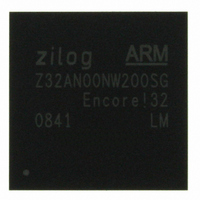
Z32AN00NW200SG Zilog, Z32AN00NW200SG Datasheet - Page 160

Z32AN00NW200SG
Manufacturer Part Number
Z32AN00NW200SG
Description
IC ARM922T MCU 200MHZ 256-BGA
Manufacturer
Zilog
Series
Encore!® 32r
Datasheet
1.Z32AN00NW200SG.pdf
(196 pages)
Specifications of Z32AN00NW200SG
Core Processor
ARM9
Core Size
16/32-Bit
Speed
200MHz
Connectivity
EBI/EMI, IrDA, SmartCard, SPI, UART/USART, USB OTG
Peripherals
DMA, LCD, Magnetic Card Reader, POR, PWM, WDT
Number Of I /o
76
Program Memory Type
ROMless
Ram Size
64K x 8
Voltage - Supply (vcc/vdd)
1.71 V ~ 3.6 V
Data Converters
A/D 4x10b
Oscillator Type
Internal
Operating Temperature
-40°C ~ 85°C
Package / Case
256-LBGA
For Use With
269-4713 - KIT DEV ENCORE 32 SERIES
Lead Free Status / RoHS Status
Lead free / RoHS Compliant
Eeprom Size
-
Program Memory Size
-
Other names
269-4717
Available stocks
Company
Part Number
Manufacturer
Quantity
Price
- Current page: 160 of 196
- Download datasheet (4Mb)
Z32AN Series Data Sheet
18.3.2 Transfer Format (SPI_CTL.PHASE = 1)
18.4 Multi-Master Operation
18.5 Slave Operation
DS0200-003
Figure 18-5 shows the timing diagram for an SPI transfer in which SPI_CTL.PHASE is set to 1. Both
polarities of SPI_CTL.CLKPOL are shown. In the case of multi-character transfers with nSS remaining
asserted between characters, the Bit0 output data will remain stable until the clock edge which starts Bit15
of the next character or until nSS de-asserts at the end of the transfer.
In a multi-master SPI system, all SCK pins are tied together, all MOSI pins are tied together, and all MISO
pins are tied together. All SPI pins must then be configured in open-drain mode by setting SPI_CTL.WOR to
prevent bus contention. At one time, only one SPI device is configured as the Master and all other SPI
devices on the bus are configured as Slaves.
The Master enables a single Slave by asserting the nSS pin on that Slave only. Then, the single Master
drives data out its SCK and MOSI pins to the Slaves’ SCK and MOSI pins (including those which are not
enabled). The enabled Slave drives data out its MISO pin to the Master’s MISO pin.
For a Master device operating in a multi-master system, if the nSS pin is configured as an input and is driven
low by another master, SPI_STAT.COL is set to ‘1’, indicating a multi-master collision (mode fault error
condition).
The SPI block is configured for Slave mode operation by:
The IRQE, PHASE, CLKPOL, and WOR bits in SPI_CTL and SPI_MOD.NUMBITS must be set to be
consistent with the other SPI devices. SPI_CTL.STR can be used to force a startup interrupt.
SPI_CTL.BIRQ and SPI_MOD.SSV are not used in slave mode. The SPI BRG is not used in slave mode.
If the slave has data to send to the master, the data must be written to SPI_DAT before the transaction
starts (first edge of SCK when nSS is asserted). If SPI_DAT is not written prior to the slave transaction,
MISO outputs whatever value was written last into SPI_DAT.
synchronization of the SPI input signals to hclk, the maximum SCK baud rate that can be supported in slave
mode is hclk divided by 8. This rate is controlled by the SPI master.
Setting SPI_CTL.SPIEN to ‘1’
Clearing SPI_CTL.MMEN to ‘0’
Clearing SPI_MOD.SSIO to ‘0’
Figure 18-5: SPI Timing (PHASE = 1)
Due to the delay resulting from
Page 147
Related parts for Z32AN00NW200SG
Image
Part Number
Description
Manufacturer
Datasheet
Request
R

Part Number:
Description:
Communication Controllers, ZILOG INTELLIGENT PERIPHERAL CONTROLLER (ZIP)
Manufacturer:
Zilog, Inc.
Datasheet:

Part Number:
Description:
KIT DEV FOR Z8 ENCORE 16K TO 64K
Manufacturer:
Zilog
Datasheet:

Part Number:
Description:
KIT DEV Z8 ENCORE XP 28-PIN
Manufacturer:
Zilog
Datasheet:

Part Number:
Description:
DEV KIT FOR Z8 ENCORE 8K/4K
Manufacturer:
Zilog
Datasheet:

Part Number:
Description:
KIT DEV Z8 ENCORE XP 28-PIN
Manufacturer:
Zilog
Datasheet:

Part Number:
Description:
DEV KIT FOR Z8 ENCORE 4K TO 8K
Manufacturer:
Zilog
Datasheet:

Part Number:
Description:
CMOS Z8 microcontroller. ROM 16 Kbytes, RAM 256 bytes, speed 16 MHz, 32 lines I/O, 3.0V to 5.5V
Manufacturer:
Zilog, Inc.
Datasheet:

Part Number:
Description:
Low-cost microcontroller. 512 bytes ROM, 61 bytes RAM, 8 MHz
Manufacturer:
Zilog, Inc.
Datasheet:

Part Number:
Description:
Z8 4K OTP Microcontroller
Manufacturer:
Zilog, Inc.
Datasheet:

Part Number:
Description:
CMOS SUPER8 ROMLESS MCU
Manufacturer:
Zilog, Inc.
Datasheet:

Part Number:
Description:
SL1866 CMOSZ8 OTP Microcontroller
Manufacturer:
Zilog, Inc.
Datasheet:

Part Number:
Description:
SL1866 CMOSZ8 OTP Microcontroller
Manufacturer:
Zilog, Inc.
Datasheet:

Part Number:
Description:
OTP (KB) = 1, RAM = 125, Speed = 12, I/O = 14, 8-bit Timers = 2, Comm Interfaces Other Features = Por, LV Protect, Voltage = 4.5-5.5V
Manufacturer:
Zilog, Inc.
Datasheet:

Part Number:
Description:
Manufacturer:
Zilog, Inc.
Datasheet:


