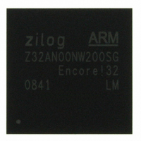
Z32AN00NW200SG Zilog, Z32AN00NW200SG Datasheet - Page 145

Z32AN00NW200SG
Manufacturer Part Number
Z32AN00NW200SG
Description
IC ARM922T MCU 200MHZ 256-BGA
Manufacturer
Zilog
Series
Encore!® 32r
Datasheet
1.Z32AN00NW200SG.pdf
(196 pages)
Specifications of Z32AN00NW200SG
Core Processor
ARM9
Core Size
16/32-Bit
Speed
200MHz
Connectivity
EBI/EMI, IrDA, SmartCard, SPI, UART/USART, USB OTG
Peripherals
DMA, LCD, Magnetic Card Reader, POR, PWM, WDT
Number Of I /o
76
Program Memory Type
ROMless
Ram Size
64K x 8
Voltage - Supply (vcc/vdd)
1.71 V ~ 3.6 V
Data Converters
A/D 4x10b
Oscillator Type
Internal
Operating Temperature
-40°C ~ 85°C
Package / Case
256-LBGA
For Use With
269-4713 - KIT DEV ENCORE 32 SERIES
Lead Free Status / RoHS Status
Lead free / RoHS Compliant
Eeprom Size
-
Program Memory Size
-
Other names
269-4717
Available stocks
Company
Part Number
Manufacturer
Quantity
Price
- Current page: 145 of 196
- Download datasheet (4Mb)
Z32AN Series Data Sheet
17.4.1 IR Transmit
17.4.2 IR Receive
17.4.3 IR Narrow Pulse Detection
DS0200-003
UART2’s TxD and Baud Rate Clock are used by the endec to generate IR_TXD that drives the infrared
transceiver. Each UART bit is 16-clocks wide. If the data to be transmitted is a ‘1’, IR_TXD remains ‘0’ for
the full 16-clock period. If the data to be transmitted is a logical 0, a 3-clock ‘1’ pulse is output following a 7-
clock ‘0’ period, which is then followed by a 6-clock ‘0’ pulse to complete the period. Data transmission is
shown below.
IR_CTL.IRXEN to ‘0’ to prevent transmitter to receiver cross-talk.
Data received on IR_RXD is decoded by the endec and passed to UART2. IR_CTL.IR_RXEN must be set to
enable the receiver decoder. The SIR data format uses half duplex communication therefore the UART must
not be allowed to transmit while the receiver decoder is enabled.
UART2 Baud Rate Clock generates the demodulated signal (RxD) that drives the UART. If the data to be
received is a ‘1’, IR_RXD remains ‘1’ for the full 16-clock period. If the data to be received is a ‘0’, a 3-clock
‘0’ pulse is output following a 7-clock ‘1’ period, which is then followed by a 6-clock ‘1’ pulse to complete the
full period. Data transmission is shown below.
The IR endec is designed to ignore pulses on IR_RXD which do not comply with IrDA pulse width
specifications. Input pulses wider than 5 baud clocks (that is, 5/16 of a bit period) are always ignored, as this
would be a violation of the maximum pulse width specified for any standard baud rate up to 115.2 kbps.
During data transmission, the IR receive function must be disabled by clearing
Figure 17-2: Infrared Data transmission
Figure 17-3: Infrared Data Reception
Page 132
Related parts for Z32AN00NW200SG
Image
Part Number
Description
Manufacturer
Datasheet
Request
R

Part Number:
Description:
Communication Controllers, ZILOG INTELLIGENT PERIPHERAL CONTROLLER (ZIP)
Manufacturer:
Zilog, Inc.
Datasheet:

Part Number:
Description:
KIT DEV FOR Z8 ENCORE 16K TO 64K
Manufacturer:
Zilog
Datasheet:

Part Number:
Description:
KIT DEV Z8 ENCORE XP 28-PIN
Manufacturer:
Zilog
Datasheet:

Part Number:
Description:
DEV KIT FOR Z8 ENCORE 8K/4K
Manufacturer:
Zilog
Datasheet:

Part Number:
Description:
KIT DEV Z8 ENCORE XP 28-PIN
Manufacturer:
Zilog
Datasheet:

Part Number:
Description:
DEV KIT FOR Z8 ENCORE 4K TO 8K
Manufacturer:
Zilog
Datasheet:

Part Number:
Description:
CMOS Z8 microcontroller. ROM 16 Kbytes, RAM 256 bytes, speed 16 MHz, 32 lines I/O, 3.0V to 5.5V
Manufacturer:
Zilog, Inc.
Datasheet:

Part Number:
Description:
Low-cost microcontroller. 512 bytes ROM, 61 bytes RAM, 8 MHz
Manufacturer:
Zilog, Inc.
Datasheet:

Part Number:
Description:
Z8 4K OTP Microcontroller
Manufacturer:
Zilog, Inc.
Datasheet:

Part Number:
Description:
CMOS SUPER8 ROMLESS MCU
Manufacturer:
Zilog, Inc.
Datasheet:

Part Number:
Description:
SL1866 CMOSZ8 OTP Microcontroller
Manufacturer:
Zilog, Inc.
Datasheet:

Part Number:
Description:
SL1866 CMOSZ8 OTP Microcontroller
Manufacturer:
Zilog, Inc.
Datasheet:

Part Number:
Description:
OTP (KB) = 1, RAM = 125, Speed = 12, I/O = 14, 8-bit Timers = 2, Comm Interfaces Other Features = Por, LV Protect, Voltage = 4.5-5.5V
Manufacturer:
Zilog, Inc.
Datasheet:

Part Number:
Description:
Manufacturer:
Zilog, Inc.
Datasheet:


