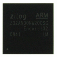
Z32AN00NW200SG Zilog, Z32AN00NW200SG Datasheet - Page 146

Z32AN00NW200SG
Manufacturer Part Number
Z32AN00NW200SG
Description
IC ARM922T MCU 200MHZ 256-BGA
Manufacturer
Zilog
Series
Encore!® 32r
Datasheet
1.Z32AN00NW200SG.pdf
(196 pages)
Specifications of Z32AN00NW200SG
Core Processor
ARM9
Core Size
16/32-Bit
Speed
200MHz
Connectivity
EBI/EMI, IrDA, SmartCard, SPI, UART/USART, USB OTG
Peripherals
DMA, LCD, Magnetic Card Reader, POR, PWM, WDT
Number Of I /o
76
Program Memory Type
ROMless
Ram Size
64K x 8
Voltage - Supply (vcc/vdd)
1.71 V ~ 3.6 V
Data Converters
A/D 4x10b
Oscillator Type
Internal
Operating Temperature
-40°C ~ 85°C
Package / Case
256-LBGA
For Use With
269-4713 - KIT DEV ENCORE 32 SERIES
Lead Free Status / RoHS Status
Lead free / RoHS Compliant
Eeprom Size
-
Program Memory Size
-
Other names
269-4717
Available stocks
Company
Part Number
Manufacturer
Quantity
Price
- Current page: 146 of 196
- Download datasheet (4Mb)
Z32AN Series Data Sheet
17.4.4 IR Jitter
17.4.5 IR Infrared Encoder/Decoder Signal Pins
17.4.6 IR Loopback Testing
DS0200-003
Minimum pulse width checking is optional, as using a slow hclk limits the ability to accurately measure
narrow pulse widths near the IrDA specification minimum of 1.41
range.
To enable checks of minimum input pulse width on IR_RXD, a non-zero value must be programmed into
IR_CTL.NARROW_PULSE. This forms the most significant four bits of the 6-bit down-counter used to
determine if an input pulse will be ignored as too narrow. The lower two counter bits are hard-coded to load
with ‘11’, resulting in a total down-count equal to ((IR_CTL.NARROW_PULSE * 4) + 3). To be accepted,
input pulses must have a width greater than or equal to the down-count value times the hclk period. The
following equation can be used to determine an appropriate setting for IR_CTL.NARROW_PULSE:
Where F
equation results in a value less than 1, IR_CTL.NARROW_PULSE must be set to 0h which enables edge
detection and ensures that valid pulses wider than W
supports a W
Due to the inherent sampling of the received IR_RXD signal by the Bit Rate Clock, some jitter is expected on
the first bit in any sequence of data. However, all subsequent bits in the received data stream are a fixed 16-
clock periods wide.
The infrared encoder/decoder signal pins (TxD2 and RxD2) are multiplexed with General-Purpose I/O
(GPIO) pins. The pins default to GPIO after reset and must be configured to use the IrDA function. For more
information, see section Chapter 20:.
Internal loopback testing is enabled by setting IR_CTL.LOOP_BACK ‘1’. External loopback testing of the
external IrDA transceiver can be accomplished by transmitting data from the UART while IR_CTL.IR_RXEN
is set to ‘1’.
SYS
is the frequency of the hclk and W
MIN
of 1.25 µs when F
SYS
is 50 MHz
MIN
is the minimum width of recognized input pulses. If this
MIN
are accepted. The field’s maximum setting of Fh
s
for the 2.4 kbps to 115.2 kbps rate
Page 133
Related parts for Z32AN00NW200SG
Image
Part Number
Description
Manufacturer
Datasheet
Request
R

Part Number:
Description:
Communication Controllers, ZILOG INTELLIGENT PERIPHERAL CONTROLLER (ZIP)
Manufacturer:
Zilog, Inc.
Datasheet:

Part Number:
Description:
KIT DEV FOR Z8 ENCORE 16K TO 64K
Manufacturer:
Zilog
Datasheet:

Part Number:
Description:
KIT DEV Z8 ENCORE XP 28-PIN
Manufacturer:
Zilog
Datasheet:

Part Number:
Description:
DEV KIT FOR Z8 ENCORE 8K/4K
Manufacturer:
Zilog
Datasheet:

Part Number:
Description:
KIT DEV Z8 ENCORE XP 28-PIN
Manufacturer:
Zilog
Datasheet:

Part Number:
Description:
DEV KIT FOR Z8 ENCORE 4K TO 8K
Manufacturer:
Zilog
Datasheet:

Part Number:
Description:
CMOS Z8 microcontroller. ROM 16 Kbytes, RAM 256 bytes, speed 16 MHz, 32 lines I/O, 3.0V to 5.5V
Manufacturer:
Zilog, Inc.
Datasheet:

Part Number:
Description:
Low-cost microcontroller. 512 bytes ROM, 61 bytes RAM, 8 MHz
Manufacturer:
Zilog, Inc.
Datasheet:

Part Number:
Description:
Z8 4K OTP Microcontroller
Manufacturer:
Zilog, Inc.
Datasheet:

Part Number:
Description:
CMOS SUPER8 ROMLESS MCU
Manufacturer:
Zilog, Inc.
Datasheet:

Part Number:
Description:
SL1866 CMOSZ8 OTP Microcontroller
Manufacturer:
Zilog, Inc.
Datasheet:

Part Number:
Description:
SL1866 CMOSZ8 OTP Microcontroller
Manufacturer:
Zilog, Inc.
Datasheet:

Part Number:
Description:
OTP (KB) = 1, RAM = 125, Speed = 12, I/O = 14, 8-bit Timers = 2, Comm Interfaces Other Features = Por, LV Protect, Voltage = 4.5-5.5V
Manufacturer:
Zilog, Inc.
Datasheet:

Part Number:
Description:
Manufacturer:
Zilog, Inc.
Datasheet:


