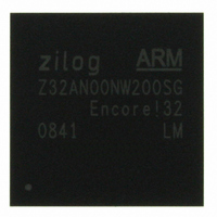
Z32AN00NW200SG Zilog, Z32AN00NW200SG Datasheet - Page 170

Z32AN00NW200SG
Manufacturer Part Number
Z32AN00NW200SG
Description
IC ARM922T MCU 200MHZ 256-BGA
Manufacturer
Zilog
Series
Encore!® 32r
Datasheet
1.Z32AN00NW200SG.pdf
(196 pages)
Specifications of Z32AN00NW200SG
Core Processor
ARM9
Core Size
16/32-Bit
Speed
200MHz
Connectivity
EBI/EMI, IrDA, SmartCard, SPI, UART/USART, USB OTG
Peripherals
DMA, LCD, Magnetic Card Reader, POR, PWM, WDT
Number Of I /o
76
Program Memory Type
ROMless
Ram Size
64K x 8
Voltage - Supply (vcc/vdd)
1.71 V ~ 3.6 V
Data Converters
A/D 4x10b
Oscillator Type
Internal
Operating Temperature
-40°C ~ 85°C
Package / Case
256-LBGA
For Use With
269-4713 - KIT DEV ENCORE 32 SERIES
Lead Free Status / RoHS Status
Lead free / RoHS Compliant
Eeprom Size
-
Program Memory Size
-
Other names
269-4717
Available stocks
Company
Part Number
Manufacturer
Quantity
Price
- Current page: 170 of 196
- Download datasheet (4Mb)
Z32AN Series Data Sheet
19.2 Receive vs. Transmit
19.3 Buffer Descriptor Addressing
19.4 USB Transaction
DS0200-003
The controller can function as a USB device or host,
and may switch modes of operation under software
control. The same data paths and buffer descriptors
are used for the transmission and reception of data.
A USB block centric nomenclature describes the
direction of data transfer between the SoC and USB.
Rx/receive is used to describe transfers that move
data from USB to memory, and Tx/transmit is used to
describe transfers that move data from memory to USB.
When the controller receives a token on an enabled endpoint it uses its DMA controller to interrogate the
BDT. The USB block reads the corresponding endpoint descriptor entry and determines if it owns the
descriptor and corresponding buffer in memory. To compute the entry point in the BDT, the
USB_BDT_PAGE registers are concatenated with the current endpoint and the TX/ODD fields to form a 32-
bit address, shown below:
When the controller moves data, it computes the BDT address. Once the BDT has been read, and if OWN =
‘1’, the controller DMAs the data to or from the buffer pointed to by the ADDR field of the descriptor. When
the token is complete, the controller updates the descriptor and clears OWN if KEEP is ‘0’.
USB_ISTAT.TDONE is set. Figure 19-2 shows how a USB token is processed.
The controller has two sources for the DMA overrun: receive FIFO overflow (transient), or the packet
received may be larger than the negotiated MaxPacket size (software bug). In the FIFO overflow case, the
31:24
23:16
15:09
08:05
Bits
04
03
02
END_POINT
BDT_PAGE
Reserved
Field
ODD
IN
Figure 19-2: USB Token Transaction
Description
USB_BDT_PAGE3 Register
USB_BDT_PAGE2 Register
USB_BDT_PAGE1 Register
End Point field from the USB TOKEN
1 for an TX transmit transfers and 0 for an RX receive transfers
This bit is maintained within the USB block SIE. It corresponds to the buffer
that is currently in use. The buffers are used in a ping-pong fashion.
Set to ‘000’
Device
Host
OUT or Setup
Rx
IN
Out or Setup
Page 157
Tx
IN
Related parts for Z32AN00NW200SG
Image
Part Number
Description
Manufacturer
Datasheet
Request
R

Part Number:
Description:
Communication Controllers, ZILOG INTELLIGENT PERIPHERAL CONTROLLER (ZIP)
Manufacturer:
Zilog, Inc.
Datasheet:

Part Number:
Description:
KIT DEV FOR Z8 ENCORE 16K TO 64K
Manufacturer:
Zilog
Datasheet:

Part Number:
Description:
KIT DEV Z8 ENCORE XP 28-PIN
Manufacturer:
Zilog
Datasheet:

Part Number:
Description:
DEV KIT FOR Z8 ENCORE 8K/4K
Manufacturer:
Zilog
Datasheet:

Part Number:
Description:
KIT DEV Z8 ENCORE XP 28-PIN
Manufacturer:
Zilog
Datasheet:

Part Number:
Description:
DEV KIT FOR Z8 ENCORE 4K TO 8K
Manufacturer:
Zilog
Datasheet:

Part Number:
Description:
CMOS Z8 microcontroller. ROM 16 Kbytes, RAM 256 bytes, speed 16 MHz, 32 lines I/O, 3.0V to 5.5V
Manufacturer:
Zilog, Inc.
Datasheet:

Part Number:
Description:
Low-cost microcontroller. 512 bytes ROM, 61 bytes RAM, 8 MHz
Manufacturer:
Zilog, Inc.
Datasheet:

Part Number:
Description:
Z8 4K OTP Microcontroller
Manufacturer:
Zilog, Inc.
Datasheet:

Part Number:
Description:
CMOS SUPER8 ROMLESS MCU
Manufacturer:
Zilog, Inc.
Datasheet:

Part Number:
Description:
SL1866 CMOSZ8 OTP Microcontroller
Manufacturer:
Zilog, Inc.
Datasheet:

Part Number:
Description:
SL1866 CMOSZ8 OTP Microcontroller
Manufacturer:
Zilog, Inc.
Datasheet:

Part Number:
Description:
OTP (KB) = 1, RAM = 125, Speed = 12, I/O = 14, 8-bit Timers = 2, Comm Interfaces Other Features = Por, LV Protect, Voltage = 4.5-5.5V
Manufacturer:
Zilog, Inc.
Datasheet:

Part Number:
Description:
Manufacturer:
Zilog, Inc.
Datasheet:


