C8051F060DK Silicon Laboratories Inc, C8051F060DK Datasheet - Page 66
C8051F060DK
Manufacturer Part Number
C8051F060DK
Description
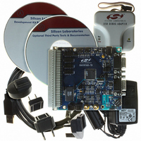
DEV KIT FOR F060/F062/F063
Manufacturer
Silicon Laboratories Inc
Type
MCUr
Datasheet
1.C8051F060-TB.pdf
(328 pages)
Specifications of C8051F060DK
Contents
Evaluation Board, Power Supply, USB Cables, Adapter and Documentation
Processor To Be Evaluated
C8051F06x
Interface Type
USB
Silicon Manufacturer
Silicon Labs
Core Architecture
8051
Silicon Core Number
C8051F060
Silicon Family Name
C8051F06x
Lead Free Status / RoHS Status
Contains lead / RoHS non-compliant
For Use With/related Products
C8051060, C8051F062 and C8051F063
Lead Free Status / Rohs Status
Lead free / RoHS Compliant
Other names
336-1214
Available stocks
Company
Part Number
Manufacturer
Quantity
Price
Company:

Part Number:
C8051F060DK
Manufacturer:
Silicon Labs
Quantity:
135


C8051F060/1/2/3/4/5/6/7
5.4.
The ADCs are calibrated for linearity, offset, and gain in production. ADC0 and ADC1 can also be indepen-
dently calibrated for each of these parameters in-system. Calibrations are initiated using bits in the ADC0
or ADC1 Configuration Register. The calibration coefficients can be accessed using the ADC Calibration
Pointer Register (ADC0CPT, Figure 5.22) and the ADC Calibration Coefficient Register (ADC0CCF,
Figure 5.23). The CPTR bits in ADC0CPT allow the ADC0CCF register to read and write specific calibra-
tion coefficients. Figure 5.19 shows the Calibration Coefficient locations.
The ADCs are calibrated for linearity in production. Under normal circumstances, no additional linearity
calibration is necessary. If linearity calibrations are desired, they can be initiated by setting the ADCnLCAL
bit to ‘1’. When the calibration is finished, the ADCnLCAL bit will be set to ‘0’ by the hardware. Linearity
Calibration Coefficients are stored in the locations shown in Figure 5.19.
Offset and gain calibrations can be performed using either internal or external voltages as calibration
sources. The ADCnSCAL bit determines whether the internal or external voltages are used in the calibra-
tion process. To ensure accuracy, offset calibration should be done prior to a gain calibration. The offset
and gain calibration coefficients are decoded in Figure 5.20. Offset calibration is initiated by setting the
ADCnOCAL bit to ‘1’. When the calibration is finished, the ADCnOCAL bit will be set to ‘0’ by the hardware.
Offset calibration can compensate for offset errors of approximately
is added to the AINnG input prior to digitization by the ADC. Gain calibration is initiated by setting the
ADCnGCAL bit to ‘1’. When the calibration is finished, the ADCnGCAL bit will be set to ‘0’ by the hardware.
Gain calibration can compensate for slope errors of approximately
the ADC’s VREF path to change the slope of the converter’s transfer function. Figure 5.21 shows how the
offset and gain values affect the analog signals used by the ADC.
66
ADC0CPT
Bits 5-0
0x00
0x12
0x13
0x14
0x15
0x16
.
.
Calibration
Offset7
Gain7
Bit7
Offset6
Gain6
Figure 5.19. Calibration Coefficient Locations
Bit6
Linearity Calibration Coefficients (locations 0x00 through 0x12)
Offset13
Offset5
Gain5
Bit5
Rev. 1.2
Offset12
Offset4
Gain12
Gain4
Bit4
ADC0CCF
Offset11
Offset3
Gain11
Gain3
Bit3
3.125% of full scale. The offset value
3.125%. The gain value is added to
Offset10
Gain10
Offset2
Gain2
Bit2
Offset1
Offset9
Gain1
Gain9
Bit1
Offset0
Offset8
Gain0
Gain8
Bit0
Related parts for C8051F060DK
Image
Part Number
Description
Manufacturer
Datasheet
Request
R

Part Number:
Description:
SMD/C°/SINGLE-ENDED OUTPUT SILICON OSCILLATOR
Manufacturer:
Silicon Laboratories Inc
Part Number:
Description:
Manufacturer:
Silicon Laboratories Inc
Datasheet:
Part Number:
Description:
N/A N/A/SI4010 AES KEYFOB DEMO WITH LCD RX
Manufacturer:
Silicon Laboratories Inc
Datasheet:
Part Number:
Description:
N/A N/A/SI4010 SIMPLIFIED KEY FOB DEMO WITH LED RX
Manufacturer:
Silicon Laboratories Inc
Datasheet:
Part Number:
Description:
N/A/-40 TO 85 OC/EZLINK MODULE; F930/4432 HIGH BAND (REV E/B1)
Manufacturer:
Silicon Laboratories Inc
Part Number:
Description:
EZLink Module; F930/4432 Low Band (rev e/B1)
Manufacturer:
Silicon Laboratories Inc
Part Number:
Description:
I°/4460 10 DBM RADIO TEST CARD 434 MHZ
Manufacturer:
Silicon Laboratories Inc
Part Number:
Description:
I°/4461 14 DBM RADIO TEST CARD 868 MHZ
Manufacturer:
Silicon Laboratories Inc
Part Number:
Description:
I°/4463 20 DBM RFSWITCH RADIO TEST CARD 460 MHZ
Manufacturer:
Silicon Laboratories Inc
Part Number:
Description:
I°/4463 20 DBM RADIO TEST CARD 868 MHZ
Manufacturer:
Silicon Laboratories Inc
Part Number:
Description:
I°/4463 27 DBM RADIO TEST CARD 868 MHZ
Manufacturer:
Silicon Laboratories Inc
Part Number:
Description:
I°/4463 SKYWORKS 30 DBM RADIO TEST CARD 915 MHZ
Manufacturer:
Silicon Laboratories Inc
Part Number:
Description:
N/A N/A/-40 TO 85 OC/4463 RFMD 30 DBM RADIO TEST CARD 915 MHZ
Manufacturer:
Silicon Laboratories Inc
Part Number:
Description:
I°/4463 20 DBM RADIO TEST CARD 169 MHZ
Manufacturer:
Silicon Laboratories Inc