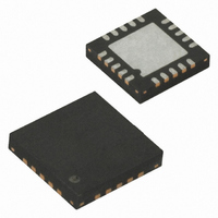
ATTINY43U-MU Atmel, ATTINY43U-MU Datasheet - Page 27

ATTINY43U-MU
Manufacturer Part Number
ATTINY43U-MU
Description
MCU AVR 4K FLASH 8MHZ 20-QFN
Manufacturer
Atmel
Series
AVR® ATtinyr
Specifications of ATTINY43U-MU
Core Processor
AVR
Core Size
8-Bit
Speed
8MHz
Connectivity
USI
Peripherals
Brown-out Detect/Reset, POR, PWM, Temp Sensor, WDT
Number Of I /o
16
Program Memory Size
4KB (2K x 16)
Program Memory Type
FLASH
Eeprom Size
64 x 8
Ram Size
256 x 8
Voltage - Supply (vcc/vdd)
1.8 V ~ 5.5 V
Data Converters
A/D 4x10b
Oscillator Type
Internal
Operating Temperature
-40°C ~ 85°C
Package / Case
20-MLF®, QFN
Processor Series
ATTINY4x
Core
AVR8
Data Bus Width
8 bit
Data Ram Size
256 B
Interface Type
SPI
Maximum Clock Frequency
8 MHz
Number Of Programmable I/os
16
Number Of Timers
2
Maximum Operating Temperature
+ 85 C
Mounting Style
SMD/SMT
3rd Party Development Tools
EWAVR, EWAVR-BL
Development Tools By Supplier
ATAVRDRAGON, ATSTK500, ATSTK600, ATAVRISP2, ATAVRONEKIT
Minimum Operating Temperature
- 40 C
On-chip Adc
10 bit, 4 Channel
For Use With
ATSTK600-TINYX3U - STK600 SOCKET/ADAPTER TINYX3U
Lead Free Status / RoHS Status
Lead free / RoHS Compliant
6.2.5
6.3
6.3.1
8048B–AVR–03/09
System Clock Prescaler
Clock Startup Sequence
Switching Time
Any clock source needs a sufficient V
cycles before it can be considered stable.
To ensure sufficient V
the device reset is released by all other reset sources. The section
on page 48
the Watchdog Oscillator and the number of cycles in the delay is set by the SUTn and CKSELn
fuse bits. The available delays are shown in
Table 6-8.
Note:
The main purpose of the delay is to keep the AVR in reset until V
The delay will not monitor the actual voltage and, hence, the user must make sure the delay time
is longer than the V
tion circuit should be used. A BOD circuit ensures there is sufficient V
reset line, and the time-out delay can then be disabled. It is not recommended to disable the
time-out delay without implementing a Brown-Out Detection circuit.
The oscillator is required to oscillate for a minimum number of cycles before the clock is consid-
ered stable. An internal ripple counter monitors the oscillator output clock, and keeps the internal
reset active for a given number of clock cycles. The reset is then released and the device will
start to execute.
The start-up sequence for the clock includes both the time-out delay and the start-up time when
the device starts up from reset. When starting up from Power-down mode, V
at a sufficient level and only the start-up time is included.
The ATtiny43U has a system clock prescaler, which means the system clock can be divided as
described in section
to lower system clock frequency and decrease the power consumption at times when require-
ments for processing power is low. This can be used with all clock source options, and it will
affect the clock frequency of the CPU and all synchronous peripherals. Clock signals clk
clk
When changing prescaler settings, the System Clock Prescaler ensures that no glitches occurs
in the clock system. It also ensures that no intermediate frequency is higher than either the clock
frequency corresponding to the previous setting or the clock frequency corresponding to the new
setting. The ripple counter of the prescaler runs at the same frequency as the undivided clock,
which may be higher than the CPU's clock frequency. Hence, even if it was readable, it is not
possible to determine the state of the prescaler, and it is not possible to predict the exact time it
takes to switch from one clock division to the other. From the time the CLKPS values are written,
ADC
Typ Time-out (V
, clk
The frequency of the Watchdog Oscillator is voltage dependent as shown in TBD.
CPU
describes the start conditions for the internal reset. The delay (t
4.1 ms
65 ms
, and clk
0 ms
Number of Watchdog Oscillator Cycles
CC
CC
“CLKPR – Clock Prescale Register” on page
= 5.0V)
FLASH
CC
rise time. If this is not possible, an internal or external Brown-Out Detec-
, the device issues an internal reset with a time-out delay (t
are divided by a factor as shown in
Typ Time-out (V
CC
to start oscillating and a minimum number of oscillating
Table
4.3 ms
69 ms
0 ms
6-8.
CC
= 3.0V)
Table 20-4 on page
CC
28. This feature can be used
has risen to a sufficient level.
“System Control and Reset”
CC
Number of Cycles
before it releases the
8K (8,192)
CC
TOUT
512
is assumed to be
0
) is timed from
158.
TOUT
) after
I/O
27
,


