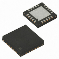
ATTINY43U-MU Atmel, ATTINY43U-MU Datasheet - Page 45

ATTINY43U-MU
Manufacturer Part Number
ATTINY43U-MU
Description
MCU AVR 4K FLASH 8MHZ 20-QFN
Manufacturer
Atmel
Series
AVR® ATtinyr
Specifications of ATTINY43U-MU
Core Processor
AVR
Core Size
8-Bit
Speed
8MHz
Connectivity
USI
Peripherals
Brown-out Detect/Reset, POR, PWM, Temp Sensor, WDT
Number Of I /o
16
Program Memory Size
4KB (2K x 16)
Program Memory Type
FLASH
Eeprom Size
64 x 8
Ram Size
256 x 8
Voltage - Supply (vcc/vdd)
1.8 V ~ 5.5 V
Data Converters
A/D 4x10b
Oscillator Type
Internal
Operating Temperature
-40°C ~ 85°C
Package / Case
20-MLF®, QFN
Processor Series
ATTINY4x
Core
AVR8
Data Bus Width
8 bit
Data Ram Size
256 B
Interface Type
SPI
Maximum Clock Frequency
8 MHz
Number Of Programmable I/os
16
Number Of Timers
2
Maximum Operating Temperature
+ 85 C
Mounting Style
SMD/SMT
3rd Party Development Tools
EWAVR, EWAVR-BL
Development Tools By Supplier
ATAVRDRAGON, ATSTK500, ATSTK600, ATAVRISP2, ATAVRONEKIT
Minimum Operating Temperature
- 40 C
On-chip Adc
10 bit, 4 Channel
For Use With
ATSTK600-TINYX3U - STK600 SOCKET/ADAPTER TINYX3U
Lead Free Status / RoHS Status
Lead free / RoHS Compliant
- Current page: 45 of 182
- Download datasheet (4Mb)
8.6.5
8.6.6
8048B–AVR–03/09
Output Capacitors
Summary
Too high resistor values may lead to Start Mode failures. See
ues” on page 45
Capacitor C
An output capacitor, C
transferred to the inductor. It is recommended to use a capacitor with high capacitance and low
Equivalent Series Resistance, ESR. A large capacitance helps to reduce the voltage ripple at
the output and a low ESR reduces voltage ripple and helps to keep the temperature of the
capacitor within limits.
The recommended capacitance at a given, steady-state load is calculated as follows:
... where T
and D is the duty cycle, calculated as shown in
The recommended ESR is calculated as follows:
A secondary output capacitor, C
The table below summarises recommended component values for a typical application.
Table 8-1.
Note:
Component
C
C
C
C
D
L
R
1
1
2
3
4
1
1
1. With these values the LPF provides a 32dB attenuation at the switching frequency of the boost
2. Application specific limits may be tighter
S
converter while permitting a supply voltage ripple of about ±200mV
2
is the switching frequency of the boost converter, V
should be located close to the device.
Boost Converter Component Values
for component recommendations and limits.
Recommended Value
C = 4.7µF
C = 100nF
C = 22µF, ESR < 100mΩ
C = 100nF
I
L = 15µH ±20%, I
R = 680Ω
R
= 1µA @ 25°C, V
3
, is required to keep the output voltage stable at times when energy is
(1)
(1)
4
, is recommended and should be placed close to the device.
MAX
C
F
OUT
= 0.5V @ 1A
= 700mA, R < 150mΩ
ESR
=
I
------------------------------------- -
LOAD
≤
“Inductor” on page
-------------- -
I
PEAK
V
V
PP
×
PP
T
S
×
D
“Boost Converter Component Val-
PP
43.
is the allowed voltage ripple
Min
100nF
15µH
10µF
1µF
(2)
Max
100nF
15µH
1kΩ
(2)
45
Related parts for ATTINY43U-MU
Image
Part Number
Description
Manufacturer
Datasheet
Request
R

Part Number:
Description:
Manufacturer:
Atmel Corporation
Datasheet:

Part Number:
Description:
Microcontrollers (MCU) 512B FL 32B SRAM TIMER ATTINY4 12MHz
Manufacturer:
Atmel

Part Number:
Description:
IC MCU AVR 512B FLASH SOT-23-6
Manufacturer:
Atmel
Datasheet:

Part Number:
Description:
IC MCU AVR 512B FLASH SOT-23-6
Manufacturer:
Atmel
Datasheet:

Part Number:
Description:
DEV KIT FOR AVR/AVR32
Manufacturer:
Atmel
Datasheet:

Part Number:
Description:
INTERVAL AND WIPE/WASH WIPER CONTROL IC WITH DELAY
Manufacturer:
ATMEL Corporation
Datasheet:

Part Number:
Description:
Low-Voltage Voice-Switched IC for Hands-Free Operation
Manufacturer:
ATMEL Corporation
Datasheet:

Part Number:
Description:
MONOLITHIC INTEGRATED FEATUREPHONE CIRCUIT
Manufacturer:
ATMEL Corporation
Datasheet:

Part Number:
Description:
AM-FM Receiver IC U4255BM-M
Manufacturer:
ATMEL Corporation
Datasheet:

Part Number:
Description:
Monolithic Integrated Feature Phone Circuit
Manufacturer:
ATMEL Corporation
Datasheet:

Part Number:
Description:
Multistandard Video-IF and Quasi Parallel Sound Processing
Manufacturer:
ATMEL Corporation
Datasheet:


