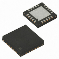
ATTINY43U-MU Atmel, ATTINY43U-MU Datasheet - Page 40

ATTINY43U-MU
Manufacturer Part Number
ATTINY43U-MU
Description
MCU AVR 4K FLASH 8MHZ 20-QFN
Manufacturer
Atmel
Series
AVR® ATtinyr
Specifications of ATTINY43U-MU
Core Processor
AVR
Core Size
8-Bit
Speed
8MHz
Connectivity
USI
Peripherals
Brown-out Detect/Reset, POR, PWM, Temp Sensor, WDT
Number Of I /o
16
Program Memory Size
4KB (2K x 16)
Program Memory Type
FLASH
Eeprom Size
64 x 8
Ram Size
256 x 8
Voltage - Supply (vcc/vdd)
1.8 V ~ 5.5 V
Data Converters
A/D 4x10b
Oscillator Type
Internal
Operating Temperature
-40°C ~ 85°C
Package / Case
20-MLF®, QFN
Processor Series
ATTINY4x
Core
AVR8
Data Bus Width
8 bit
Data Ram Size
256 B
Interface Type
SPI
Maximum Clock Frequency
8 MHz
Number Of Programmable I/os
16
Number Of Timers
2
Maximum Operating Temperature
+ 85 C
Mounting Style
SMD/SMT
3rd Party Development Tools
EWAVR, EWAVR-BL
Development Tools By Supplier
ATAVRDRAGON, ATSTK500, ATSTK600, ATAVRISP2, ATAVRONEKIT
Minimum Operating Temperature
- 40 C
On-chip Adc
10 bit, 4 Channel
For Use With
ATSTK600-TINYX3U - STK600 SOCKET/ADAPTER TINYX3U
Lead Free Status / RoHS Status
Lead free / RoHS Compliant
8.3
8.3.1
40
Output Voltage versus Load Current
ATtiny43U
Active Regulated Mode
As current consumption goes below I
lated Mode to Active Low Current Mode. After this, the more the load current is decreased the
longer the discharge time of the output capacitor, i.e. the time when the converter is not switch-
ing, will be. Similarly, the charge time, i.e. the time when the converter is switching, will be
shorter. Note that in Active Low Current Mode only the last part of the rising/switching slope is
changed.
Charge time can be minimised by forcing the device into Full Duty Cycle mode of operation (see
“Full Duty Cycle” on page
When load current increases above I
The output voltage of the boost converter depends on the amount of load and method of duty
cycle control.
In Active Mode the boost converter operates in one of two sub-modes called (Active) Regulated
Mode and (Active) Low Current Mode. In Regulated Mode the emphasis is on maintaining a sta-
ble output voltage, while in Low Current Mode the emphasis is on minimising current
consumption. The converter always enters Active Regulated Mode at first and switches to Low
Current Mode automatically when required but it is possible to design the application such that
the converter always stays in Active Regulated Mode.
The boost converter goes from Active Regulated Mode to Active Low Current Mode when the
duty cycle reaches its minimum and the output voltage reaches its maximum. At this point the
converter stops switching and the output voltage starts to fall. The converter starts switching
again when the output voltage has fallen to the low limit defined for Low Current Mode. If load
current increases sufficiently the converter will go back from Active Low Current Mode to Active
Regulated Mode. See
The boost converter goes back to Start Mode if output voltage drops below V
over from Stop Mode if input voltage drops below V
so.
This is the default method of operation in Active Mode. The converter will remain in this mode
provided that load current is sufficiently high. See
In this mode of operation the output voltage is constantly regulated. This means a stable output
voltage with a low amplitude, high frequency ripple superimposed. See
7 on page
The firmware can instruct the converter to leave this mode and enter Stop Mode. See
Control of Boost Converter” on page
159.
Figure 21-1 on page
41).
MS
42.
MS
the converter goes back to Active Regulated Mode.
(see
165.
Figure
“Active Low Current Mode” on page
STOP
8-5) the converter goes from Active Regu-
, or when instructed by firmware to do
Figure 8-6
BOOST
and
8048B–AVR–03/09
, and starts
“Software
Table 20-
41.


