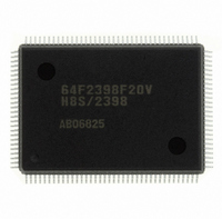
DF2398F20V Renesas Electronics America, DF2398F20V Datasheet - Page 121

DF2398F20V
Manufacturer Part Number
DF2398F20V
Description
IC H8S/2300 MCU FLASH 128QFP
Manufacturer
Renesas Electronics America
Series
H8® H8S/2300r
Specifications of DF2398F20V
Core Processor
H8S/2000
Core Size
16-Bit
Speed
20MHz
Connectivity
SCI, SmartCard
Peripherals
DMA, POR, PWM, WDT
Number Of I /o
87
Program Memory Size
256KB (256K x 8)
Program Memory Type
FLASH
Ram Size
8K x 8
Voltage - Supply (vcc/vdd)
4.5 V ~ 5.5 V
Data Converters
A/D 8x10b; D/A 2x8b
Oscillator Type
Internal
Operating Temperature
-20°C ~ 75°C
Package / Case
128-QFP
For Use With
YR0K42378FC000BA - KIT EVAL FOR H8S/2378
Lead Free Status / RoHS Status
Lead free / RoHS Compliant
Eeprom Size
-
Available stocks
Company
Part Number
Manufacturer
Quantity
Price
Company:
Part Number:
DF2398F20V
Manufacturer:
Renesas Electronics America
Quantity:
135
Company:
Part Number:
DF2398F20V
Manufacturer:
Renesas Electronics America
Quantity:
10 000
- Current page: 121 of 1049
- Download datasheet (5Mb)
Note: * Lower 16 bits of the start address.
5.4
5.4.1
Interrupt operations in the H8S/2357 Group differ depending on the interrupt control mode.
NMI interrupts are accepted at all times except in the reset state and the hardware standby state. In the case of IRQ
interrupts and on-chip supporting module interrupts, an enable bit is provided for each interrupt. Clearing an enable bit to
0 disables the corresponding interrupt request. Interrupt sources for which the enable bits are set to 1 are controlled by the
interrupt controller.
Table 5-5 shows the interrupt control modes.
The interrupt controller performs interrupt control according to the interrupt control mode set by the INTM1 and INTM0
bits in SYSCR, the priorities set in IPR, and the masking state indicated by the I and UI bits in the CPU’s CCR, and bits I2
to I0 in EXR.
Table 5-5
Interrupt Operation
Interrupt Control Modes and Interrupt Operation
Interrupt Source
ERI0 (receive error 0)
RXI0 (reception data full 0)
TXI0 (transmit data empty 0)
TEI0 (transmission end 0)
ERI1 (receive error 1)
RXI1 (reception data full 1)
TXI1 (transmit data empty 1)
TEI1 (transmission end 1)
ERI2 (receive error 2)
RXI2 (reception data full 2)
TXI2 (transmit data empty 2)
TEI2 (transmission end 2)
Interrupt
Control Mode INTM1 INTM0 Registers
0
—
2
—
Interrupt Control Modes
0
1
SYSCR
0
1
0
1
Priority Setting
—
—
IPR
—
Origin of
SCI
channel 1
SCI
channel 2
Interrupt
Source
SCI
channel 0
Vector
Number
80
81
82
83
84
85
86
87
88
89
90
91
Interrupt
Mask Bits Description
I
—
I2 to I0
—
Vector
Address*
Advanced
Mode
H'0140
H'0144
H'0148
H'014C
H'0150
H'0154
H'0158
H'015C
H'0160
H'0164
H'0168
H'016C
Interrupt mask control is
performed by the I bit.
Setting prohibited
8-level interrupt mask control
is performed by bits I2 to I0.
8 priority levels can be set with
IPR.
Setting prohibited
Rev.6.00 Oct.28.2004 page 91 of 1016
IPR
IPRJ2 to 0
IPRK6 to 4
IPRK2 to 0
Priority
High
Low
REJ09B0138-0600H
Related parts for DF2398F20V
Image
Part Number
Description
Manufacturer
Datasheet
Request
R

Part Number:
Description:
CONN PLUG 12POS DUAL 0.5MM SMD
Manufacturer:
Hirose Electric Co Ltd
Datasheet:

Part Number:
Description:
CONN PLUG 18POS DUAL 0.5MM SMD
Manufacturer:
Hirose Electric Co Ltd
Datasheet:

Part Number:
Description:
CONN PLUG 14POS DUAL 0.5MM SMD
Manufacturer:
Hirose Electric Co Ltd
Datasheet:

Part Number:
Description:
CONN RECEPT 20POS DUAL 0.5MM SMD
Manufacturer:
Hirose Electric Co Ltd
Datasheet:

Part Number:
Description:
CONN PLUG 16POS DUAL 0.5MM SMD
Manufacturer:
Hirose Electric Co Ltd
Datasheet:

Part Number:
Description:
CONN RECEPT 16POS DUAL 0.5MM SMD
Manufacturer:
Hirose Electric Co Ltd
Datasheet:

Part Number:
Description:
CONN PLUG 20POS DUAL 0.5MM SMD
Manufacturer:
Hirose Electric Co Ltd
Datasheet:

Part Number:
Description:
CONN PLUG 30POS DUAL 0.5MM SMD
Manufacturer:
Hirose Electric Co Ltd
Datasheet:

Part Number:
Description:
CONN RECEPT 30POS DUAL 0.5MM SMD
Manufacturer:
Hirose Electric Co Ltd
Datasheet:

Part Number:
Description:
CONN PLUG 40POS DUAL 0.5MM SMD
Manufacturer:
Hirose Electric Co Ltd
Datasheet:

Part Number:
Description:
KIT STARTER FOR M16C/29
Manufacturer:
Renesas Electronics America
Datasheet:

Part Number:
Description:
KIT STARTER FOR R8C/2D
Manufacturer:
Renesas Electronics America
Datasheet:

Part Number:
Description:
R0K33062P STARTER KIT
Manufacturer:
Renesas Electronics America
Datasheet:

Part Number:
Description:
KIT STARTER FOR R8C/23 E8A
Manufacturer:
Renesas Electronics America
Datasheet:

Part Number:
Description:
KIT STARTER FOR R8C/25
Manufacturer:
Renesas Electronics America
Datasheet:


