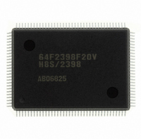
DF2398F20V Renesas Electronics America, DF2398F20V Datasheet - Page 17

DF2398F20V
Manufacturer Part Number
DF2398F20V
Description
IC H8S/2300 MCU FLASH 128QFP
Manufacturer
Renesas Electronics America
Series
H8® H8S/2300r
Specifications of DF2398F20V
Core Processor
H8S/2000
Core Size
16-Bit
Speed
20MHz
Connectivity
SCI, SmartCard
Peripherals
DMA, POR, PWM, WDT
Number Of I /o
87
Program Memory Size
256KB (256K x 8)
Program Memory Type
FLASH
Ram Size
8K x 8
Voltage - Supply (vcc/vdd)
4.5 V ~ 5.5 V
Data Converters
A/D 8x10b; D/A 2x8b
Oscillator Type
Internal
Operating Temperature
-20°C ~ 75°C
Package / Case
128-QFP
For Use With
YR0K42378FC000BA - KIT EVAL FOR H8S/2378
Lead Free Status / RoHS Status
Lead free / RoHS Compliant
Eeprom Size
-
Available stocks
Company
Part Number
Manufacturer
Quantity
Price
Company:
Part Number:
DF2398F20V
Manufacturer:
Renesas Electronics America
Quantity:
135
Company:
Part Number:
DF2398F20V
Manufacturer:
Renesas Electronics America
Quantity:
10 000
- Current page: 17 of 1049
- Download datasheet (5Mb)
5.3
5.4
5.5
5.6
Section 6 Bus Controller...................................................................................................................103
6.1
6.2
6.3
6.4
5.2.2
5.2.3
5.2.4
5.2.5
Interrupt Sources......................................................................................................................................................... 87
5.3.1
5.3.2
5.3.3
Interrupt Operation ..................................................................................................................................................... 91
5.4.1
5.4.2
5.4.3
5.4.4
5.4.5
Usage Notes ................................................................................................................................................................99
5.5.1
5.5.2
5.5.3
5.5.4
DTC and DMAC Activation by Interrupt................................................................................................................. 100
5.6.1
5.6.2
5.6.3
5.6.4
Overview................................................................................................................................................................... 103
6.1.1
6.1.2
6.1.3
6.1.4
Register Descriptions................................................................................................................................................108
6.2.1
6.2.2
6.2.3
6.2.4
6.2.5
6.2.6
6.2.7
6.2.8
6.2.9
Overview of Bus Control..........................................................................................................................................121
6.3.1
6.3.2
6.3.3
6.3.4
6.3.5 Chip Select Signals ..........................................................................................................................................124
Basic Bus Interface................................................................................................................................................... 125
6.4.1
6.4.2
6.4.3
6.4.4
Interrupt Priority Registers A to K (IPRA to IPRK) ..................................................................................... 84
IRQ Enable Register (IER) ........................................................................................................................... 85
IRQ Sense Control Registers H and L (ISCRH, ISCRL)..............................................................................86
IRQ Status Register (ISR) ............................................................................................................................. 86
External Interrupts......................................................................................................................................... 87
Internal Interrupts ..........................................................................................................................................88
Interrupt Exception Handling Vector Table ..................................................................................................88
Interrupt Control Modes and Interrupt Operation ......................................................................................... 91
Interrupt Control Mode 0............................................................................................................................... 93
Interrupt Control Mode 2............................................................................................................................... 95
Interrupt Exception Handling Sequence ....................................................................................................... 97
Interrupt Response Times..............................................................................................................................98
Contention between Interrupt Generation and Disabling..............................................................................99
Instructions that Disable Interrupts ............................................................................................................... 99
Times when Interrupts are Disabled............................................................................................................100
Interrupts during Execution of EEPMOV Instruction................................................................................. 100
Overview ..................................................................................................................................................... 100
Block Diagram............................................................................................................................................. 101
Operation ..................................................................................................................................................... 101
Note on Use ................................................................................................................................................. 102
Features ....................................................................................................................................................... 103
Block Diagram............................................................................................................................................. 105
Pin Configuration ........................................................................................................................................106
Register Configuration ................................................................................................................................107
Bus Width Control Register (ABWCR) ......................................................................................................108
Access State Control Register (ASTCR)..................................................................................................... 109
Wait Control Registers H and L (WCRH, WCRL)..................................................................................... 110
Bus Control Register H (BCRH)................................................................................................................. 113
Bus Control Register L (BCRL)..................................................................................................................114
Memory Control Register (MCR) ............................................................................................................... 116
DRAM Control Register (DRAMCR)......................................................................................................... 118
Refresh Timer/Counter (RTCNT) ............................................................................................................... 119
Refresh Time Constant Register (RTCOR)................................................................................................. 120
Area Partitioning ......................................................................................................................................... 121
Bus Specifications ....................................................................................................................................... 122
Memory Interfaces....................................................................................................................................... 123
Advanced Mode........................................................................................................................................... 123
Overview ..................................................................................................................................................... 125
Data Size and Data Alignment ....................................................................................................................125
Valid Strobes ..............................................................................................................................................127
Basic Timing ............................................................................................................................................... 128
Rev.6.00 Oct.28.2004 page xi of xxiv
REJ09B0138-0600H
Related parts for DF2398F20V
Image
Part Number
Description
Manufacturer
Datasheet
Request
R

Part Number:
Description:
CONN PLUG 12POS DUAL 0.5MM SMD
Manufacturer:
Hirose Electric Co Ltd
Datasheet:

Part Number:
Description:
CONN PLUG 18POS DUAL 0.5MM SMD
Manufacturer:
Hirose Electric Co Ltd
Datasheet:

Part Number:
Description:
CONN PLUG 14POS DUAL 0.5MM SMD
Manufacturer:
Hirose Electric Co Ltd
Datasheet:

Part Number:
Description:
CONN RECEPT 20POS DUAL 0.5MM SMD
Manufacturer:
Hirose Electric Co Ltd
Datasheet:

Part Number:
Description:
CONN PLUG 16POS DUAL 0.5MM SMD
Manufacturer:
Hirose Electric Co Ltd
Datasheet:

Part Number:
Description:
CONN RECEPT 16POS DUAL 0.5MM SMD
Manufacturer:
Hirose Electric Co Ltd
Datasheet:

Part Number:
Description:
CONN PLUG 20POS DUAL 0.5MM SMD
Manufacturer:
Hirose Electric Co Ltd
Datasheet:

Part Number:
Description:
CONN PLUG 30POS DUAL 0.5MM SMD
Manufacturer:
Hirose Electric Co Ltd
Datasheet:

Part Number:
Description:
CONN RECEPT 30POS DUAL 0.5MM SMD
Manufacturer:
Hirose Electric Co Ltd
Datasheet:

Part Number:
Description:
CONN PLUG 40POS DUAL 0.5MM SMD
Manufacturer:
Hirose Electric Co Ltd
Datasheet:

Part Number:
Description:
KIT STARTER FOR M16C/29
Manufacturer:
Renesas Electronics America
Datasheet:

Part Number:
Description:
KIT STARTER FOR R8C/2D
Manufacturer:
Renesas Electronics America
Datasheet:

Part Number:
Description:
R0K33062P STARTER KIT
Manufacturer:
Renesas Electronics America
Datasheet:

Part Number:
Description:
KIT STARTER FOR R8C/23 E8A
Manufacturer:
Renesas Electronics America
Datasheet:

Part Number:
Description:
KIT STARTER FOR R8C/25
Manufacturer:
Renesas Electronics America
Datasheet:


