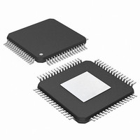
PIC24FJ256DA206-I/MR Microchip Technology, PIC24FJ256DA206-I/MR Datasheet - Page 254

PIC24FJ256DA206-I/MR
Manufacturer Part Number
PIC24FJ256DA206-I/MR
Description
MCU PIC 16BIT FLASH 256K 64VQFN
Manufacturer
Microchip Technology
Series
PIC® 24Fr
Specifications of PIC24FJ256DA206-I/MR
Program Memory Type
FLASH
Program Memory Size
256KB (85.5K x 24)
Package / Case
64-VFQFN, Exposed Pad
Core Processor
PIC
Core Size
16-Bit
Speed
32MHz
Connectivity
I²C, IrDA, SPI, UART/USART, USB OTG
Peripherals
Brown-out Detect/Reset, GFX, LVD, POR, PWM, WDT
Number Of I /o
52
Ram Size
96K x 8
Voltage - Supply (vcc/vdd)
2.2 V ~ 3.6 V
Data Converters
A/D 16x10b
Oscillator Type
Internal
Operating Temperature
-40°C ~ 85°C
Processor Series
PIC24FJ
Core
PIC
Data Bus Width
16 bit
Data Ram Size
96 KB
Interface Type
UART, SPI, USB, I2C, RS-485, RS-232
Maximum Clock Frequency
32 MHz
Number Of Programmable I/os
23
Number Of Timers
5
Operating Supply Voltage
3.6 V
Maximum Operating Temperature
+ 85 C
Mounting Style
SMD/SMT
3rd Party Development Tools
52713-733, 52714-737, 53276-922, EWDSPIC
Development Tools By Supplier
PG164130, DV164035, DV244005, DV164005, AC164127-4, AC164127-6, AC164139, DM240001, DM240312, DV164039
Minimum Operating Temperature
- 40 C
Lead Free Status / RoHS Status
Lead free / RoHS Compliant
Eeprom Size
-
Lead Free Status / Rohs Status
Lead free / RoHS Compliant
- Current page: 254 of 408
- Download datasheet (4Mb)
PIC24FJ256DA210 FAMILY
18.7
There are a total of 37 memory mapped registers asso-
ciated with the USB OTG module. They can be divided
into four general categories:
• USB OTG Module Control (12)
• USB Interrupt (7)
• USB Endpoint Management (16)
• USB V
This total does not include the (up to) 128 BD registers
in
Register 18-1 and Register 18-2, are shown separately
in Section 18.2 “USB Buffer Descriptors and the
BDT”.
DS39969B-page 254
the
USB OTG Module Registers
BUS
BDT.
Power Control (2)
Their
prototypes,
described
in
With the exception of U1PWMCON and U1PWMRRS,
all USB OTG registers are implemented in the Least
Significant Byte of the register. Bits in the upper byte
are unimplemented and have no function. Note that
some registers are instantiated only in Host mode,
while other registers have different bit instantiations
and functions in Device and Host modes.
The registers described in the following sections are
those that have bits with specific control and configura-
tion features. The following registers are used for data
or address values only:
• U1BDTP1: Specifies the 256-word page in data
• U1FRML and U1FRMH: Contains the 11-bit byte
• U1PWMRRS: Contains the 8-bit value for PWM
RAM used for the BDT; 8-bit value with bit 0 fixed
as ‘0’ for boundary alignment.
counter for the current data frame.
duty cycle bits<15:8> and PWM period
bits<7:0> for the V
BUS
2010 Microchip Technology Inc.
boost assist PWM module.
Related parts for PIC24FJ256DA206-I/MR
Image
Part Number
Description
Manufacturer
Datasheet
Request
R

Part Number:
Description:
Manufacturer:
Microchip Technology Inc.
Datasheet:

Part Number:
Description:
Manufacturer:
Microchip Technology Inc.
Datasheet:

Part Number:
Description:
Manufacturer:
Microchip Technology Inc.
Datasheet:

Part Number:
Description:
Manufacturer:
Microchip Technology Inc.
Datasheet:

Part Number:
Description:
Manufacturer:
Microchip Technology Inc.
Datasheet:

Part Number:
Description:
Manufacturer:
Microchip Technology Inc.
Datasheet:

Part Number:
Description:
Manufacturer:
Microchip Technology Inc.
Datasheet:

Part Number:
Description:
Manufacturer:
Microchip Technology Inc.
Datasheet:


